Layout

Layout
|
Setting |
Description |
|
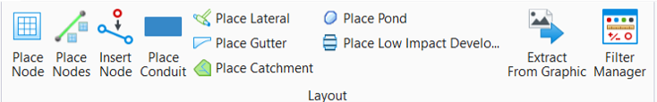
Places utility point features such as catch basins, manholes, valves, bends and headwalls. |
|
|
Creates nodes that are equally spaced along a linear element. |
|
|
Inserts a node. |
|
|
Creates conduit links by connecting two independent nodes. |
|
|
Places utility point features such as catch basins, manholes, valves, and etc. while simultaneously creating a connecting conduit to a trunk line. |
|
|
Defines the path of bypass flow and the shape of gutter between inlets of a drainage network. |
|
|
Defines an area for a catchment. |
|
|
Creates a pond. |
|
|
Creates a low impact development. |
|
|
Creates utility models from graphic elements. |
|
|
Allows the creation and management of filters and filter groups. |


Profile Runs
|
Setting |
Description |
|
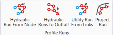
Hydraulic Run From Node |
Creates a profile run from a selected node to the outfall, or between two selected nodes. This tool only works on hydraulic (i.e. storm or sanitary) networks. |
|
Hydraulic Runs to Outfall |
Creates a profile run for every path, from the most upstream nodes to the outfall. These paths are sometimes known as trunks or branches. This tool only works on hydraulic (i.e. storm or sanitary) systems. |
|
Utility Run From Links |
Creates a profile run from selected links, for any type of utility (e.g. storm, communications, electric, etc.) The links must be consecutive, without gaps between them. |
|
Project Run |
Projects a profile run created using the tools above onto a linear element, which could be a road centreline, or another profile run. |