Place Conduit
Place Conduit creates a conduit between two independent nodes.
The characteristics of the Place Conduit command are:
- Utilize a feature definition which defines conduit characteristics
- Will create the conduit to connection points defined in the nodes
- Will model the conduit in 3D
Interface
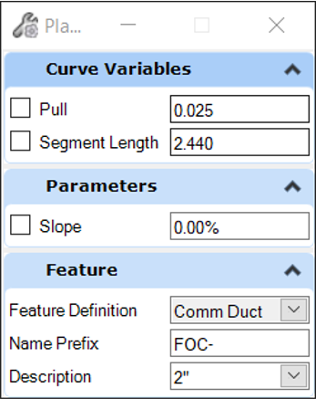
- Pull and Segment Length – used to define a curved conduit layout by applying a deflection at each joint. Disabled except when entering curved conduit mode and radius is zero.
- Radius – radius of a curved conduit layout. Disabled except when entering curved conduit mode and pull/segment length are zero
- Slope – user defined slope along the conduit
- Feature Definition – Defines the feature definition to be assigned to the new node. User can choose feature definition by:
- Description – A conduit feature definition can contain multiple definitions for size. The available, defined dimensional variations are available here.
Elevations
Elevations at the conduit ends are determined as follows:
- The Conduit Feature definition for a utility (non-hydraulic) line contains a minimum depth of cover property, in the conduit table. For a drainage (hydraulic) conduit, the depth of cover is read from the Default Design Constraints, unless this is overridden in the prototype for the Conduit Feature Definition, by changing Set Local Design Constraint to True, then specifying the minimum depth of cover there. The minimum depth of cover will result in an elevation at the end points. If Consider Cover Along Pipe Length is checked on in Default Design Constraints, then the minimum depth of cover will be adhered over the whole length of the pipe - not just at the end points.
- If you enter a slope on second prompt the slope may result in an elevation on the second node which is different than the minimum depth of cover for the conduit or the node cell.
- The nodes will have an invert elevation point defined in the bottom 3D cell. This is the elevation that will be used in absence of other information.
Properties
When selected, the properties of a conduit will be shown and editable in the MicroStation property panel (Element Info and Quick Properties).
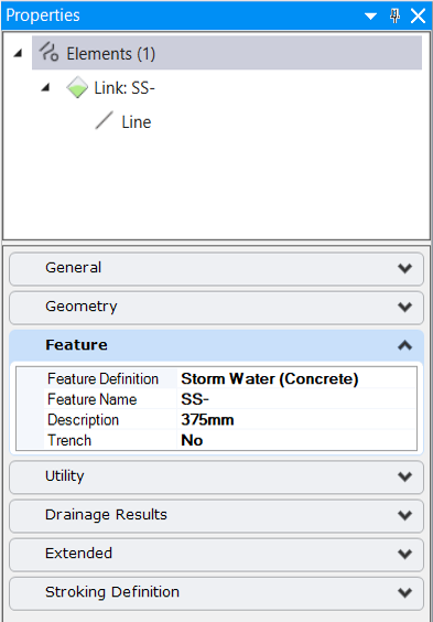
- Names of the start and stop nodes. These are where the conduit connects.
- Invert Elevations of the conduit at each end.
- Diameter or Rise/Span – the dimensions which define the conduit.
- Feature name and feature definition.
- Description – Conduit size in a drop down list. The user may change size by choosing any entry in the table. Table consists of all entries defined in the conduit table for the feature definition.
Open Utility Properties provides a shortcut to a second properties dialog, which provides more details.
You can find further information here, Utilities View > Element Views > Utilities Properties.
Manipulators
When the conduit is selected the manipulators as shown below will be presented. These are presented only in 2d space.
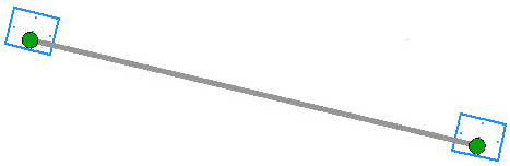
The presented manipulators will function in plan and profile as follows:
- Reconnect Link (plan only) - click on this handle to move the conduit end point. In plan the end point moves and user can click on another connection point on the same node or a different node.
- Drag Start/Stop Invert (profile only) - click on this handle to adjust the elevation for the conduit by moving it up and down the connected node. Not available if the Set Invert to Start / Stop Hydraulic properties are set to True.
- Slope - a text manipulator for the slope of the conduit. "If Show OpenFlows Calculated Slope", in the Drainage and Utilities category of File > Settings> User > Preferences > View Options - Civil > dialog is set to False, then the slope is calculated using the length of the conduit between the connection regions. If it is set to True, then the slope is calculated using the length of the conduit between the centres of the connected nodes. This value will match the Slope (Calculated) value in the Drainage properties. It is read-only.
- Elevations - text manipulators for elevations at each end. Not available if the Set Invert to Start / Stop Hydraulic properties are set to True.