Stair Placement Settings

| Toolbar utility | Use |
|---|---|
Stairs:

|
The Stair Selector lists all datagroup
catalog stairs available for placement. The Stair Selector also enables you to
define new stair instances within the datagroup catalog; copy existing
datagroup catalog stair instances to create a new instance; and modify existing
datagroup catalog stair instances.
The Stair Selector drop down menu displays the active
datagroup stair instances.
Also lists additional stair assemblies those defined
locally.
The stair catalog items are stored in DataGroup System and
are accessible through
|
Stair Properties

|
The Stair Property panel tool icon opens the Stair Properties dialog, displaying properties for the active stair definition. Here you can review or modify stair attributes prior to placement. There the Stair Properties menu bar tools are used to create and modify stair definitions or reset to default values. |
Stair Configuration

|
Standard stair configurations are selected
from the Stair Configuration drop down menu prior to placement.
The Dynamic Placement allows you to define unique stair
configurations through placement of stair and landing segments. Enables the
Placement Profile and Stair/Landing Segments options on the toolbar.
|
Stair Alignment

|
Sets the controlling anchor point for
stair placement.
The setting aids when placing a stair along walls.
Uses the walkline for placement.
Left Base of stairs, as if approaching the stair to go
up.
Base is the bottom of the stairs with the direction of
travel going up.
Top is at the top of the flight of the stairs with direction of travel going down. Landing is the intermediate platform, the first segment defines the starting (base) stair segment, in a direction of travel to down from the landing and the second segment defines the ending (top) stair segment in a direction of travel of up from the landing. |
| Stair Width | Uses the active datagroup catalog instance
for width. You can also enter a value for width during placement, using the
active working units. Manually entered values are not added to the datagroup
catalog’s instance definition. Datagroup catalog values are added using
theStair
Properties panel.
A list of the most recently used widths are available through MRU to leverage previous entries. |
| Stair Height | Sets the method for defining the height of
a flight of stairs. The toolbar changes to reflect the settings options for
each method. The methods are:
|
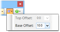
Stair Offset

|
Defines a base or top offset(s) in placement of the stair
assembly. It can be in either positive or negative direction.
For Constrained Floor, both top and base offsets are applicable. The offsets add or subtract to the floor manager values. Before this option could apply you must activate a floor in the Floor Selector, otherwise a constraint warning prompts a message no active floor defined or floor to floor distance is zero. The offsets set here apply the values to Offset properties in the Placement tab in the Stair Properties panel. |
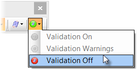
Validation

|
Monitors changes made through the heads-up
display, provides warnings and status, and notifies you if the stair assembly
definition is valid.
Sets validation options:
Note: Validation
warning icon keeps blinking until the settings are adjusted within the defined
constraint rules. Clicking on the blinking icon opens the alert message to
preview the warning details and recommendations.
The validation options are set in the Stair properties panel by defining the constraint values in the Constraint Controls tab. |


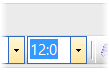 When this method is
selected, a distance setting is available. A list of the most recently used
heights/distances are available through MRU to leverage previous entries.
When this method is
selected, a distance setting is available. A list of the most recently used
heights/distances are available through MRU to leverage previous entries.