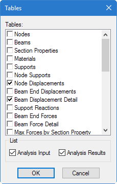
You can reopen any closed tables from the
Tables dialog, which is opened by
selecting the
Tables tool in the
Windows group on the
View ribbon tab.
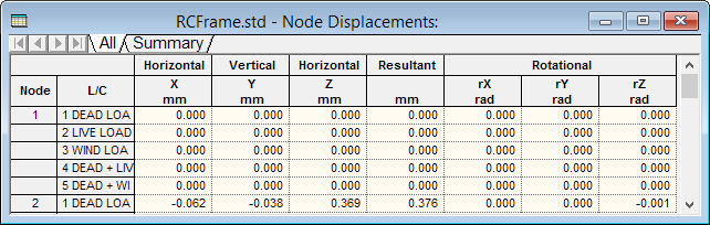
The Node Displacements table
Figure 1.
Setting
Description
All
This tab presents all nodal displacements in tabular
form for all load cases and all degrees of freedom.
Setting
Description
Summary
This tab, shown in the figure below, presents the
maximum and minimum nodal displacements (translational and rotational) for each
degree of freedom. All nodes and all Load Cases specified during the Results
Setup are considered. Maximum values for all degrees of freedom are presented
with the corresponding Node of occurrence and Load Case number (L/C).
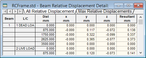
The Beam Relative Displacement Detail table
Figure 2.
Setting
Description
All
The
All
tab presents the displacements of members at
intermediate section points. All specified members and all specified load cases
are included. The table shows displacements along the local axes of the
members, as well as their resultants.
Max Displacements
The
Max Displacements tab presents the
summary of maximum sectional displacements (see figure below). This table
includes the maximum displacement values and location of its occurrence along
the member, for all specified members and all specified load cases. The table
also provides the ratio of the span length of the member to the resultant
maximum section displacement of the member.