| Preview Models list |
A list of mesh prototypes are listed here. Multiple settings may
be experimented with here to obtain the desired surface mesh before merging
with the base model. Selecting the meshed surface name displays the overall
model parameters. Selecting a "child" item in the list (e.g., boundary,
openings, etc.) displays the parameters for that item.
- model name
Selecting the name of the model displays the overall model
parameters, which were initially set in the Add Parametric
Model
dialog.
- Boundary Connectivity - The
following methods are available for parametric model boundaries:
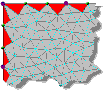
| None - Meshing will be
done without creating any nodes along the edges of the boundary
we defined. This also ignores any boundary condition (divisions
or densities) and the element size. Thus, the entire distance
between two sequential nodes will form the side of one element.
In most cases, this can lead to poor quality elements, and is
best avoided. |
No divisions
|
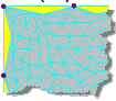
| Optimize - (Default,
recommended) Automatic boundary divisions to the target element
size. |
Optimized
|
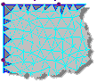
Define - Each boundary between the selected
nodes will be sub-divided into the specified number of segments
given in Number of
segments/boundary.Note: The default
value of 0 will result in the application using the
Target element size to generate
segments along edges (sim. to the
Optimize option). A value of 1
will result in no segmentation between nodes (sim. to the
None option).
|
Equal number of divisions
|
- Target Element Size - the target element size
to use for meshing, in the given units of length
- Mesh the selected plate element - the shape of
the element used:
-
Quad - quadrilateral elements with four
boundary nodes
-
Triangular - triangular elements with three
boundary nodes
-
Boundary
Selecting a Boundary Point/Edge displays the points' 3D coordinates
(which cannot be modified) and two additional parameters which can be
edited:
-
Division - When a Mesh Type is
selected as Optimize, this value is used to
identify the number of divisions along the boundary edge from the
selected node to the next defined point on the boundary.
-
Density - When a Mesh Type is
selected as Define, this value is used as a
biasing parameter. The larger the value, the denser the mesh around
the boundary point.
-
Openings
Openings can be added by selecting the Openings heading and clicking the
Add button. Either polygonal or circular
openings can be added as described above. Both opening types have options
that can be edited.
-
Polygonal
Selecting a Polygonal opening definition in the dialog displays the
control point coordinates that form the opening (which cannot be
edited). Each point includes two additional parameters which can be
edited:
Division - When a Mesh Type is
selected as Optimize, this value is used to
identify the number of divisions along the boundary edge from the
selected node to the next defined point on the boundary.
Density - When a Mesh Type is
selected as Define, this value is used as a
biasing parameter. The larger the value, the denser the mesh around
the opening point.
-
Circular
Selecting a Circular opening definition in the dialog displays the
circle center coordinates that form the opening (which cannot be
edited). Each point includes three additional parameters which can
be edited:
Radius - This defines the size of the
opening. This value is used by all Mesh Types.
Division - This is used to define the
number of segments that form the circle and is used by all Mesh
Types.
Density - When a Mesh Type is
selected as Define, this value is used as a
biasing parameter. The larger the value, the denser the mesh around
each point that forms the opening.
-
Regions
Selecting a Region definition in the dialog displays the control point
coordinates that form the region (which cannot be edited). Each point
includes two additional parameters which can be edited:
-
Division - When a Mesh Type is
selected as Optimize, this value is used to
identify the number of divisions along the boundary edge from the
selected node to the next defined point on the boundary.
-
Density - When a Mesh Type is
selected as Define, this value is used as a
biasing parameter. The larger the value, the denser the mesh around
the point on the region.
Note: The control points for an
OPENING or REGION cannot lie on the surface
boundary.
-
Density Points
Selecting a Density Point definition in the dialog displays the coordinate of that point, which cannot be edited and a single parameters which can be edited:
-
Density Lines
Density lines are defined by two points. Selecting a Density Line definition in the dialog displays the two coordinates of the line which cannot be edited and two additional parameters which can:
-
Division - This is displayed on the first
point that defines the density line, but applies to the line
between both points. This value is used to identify the number of
divisions along the density line and is used by all mesh
types.
-
Density - When a Mesh Type is
selected as Define, this value is used as a
biasing parameter. The larger the value, the denser the mesh around
the point on the density line.
|
| Parameters table |
Displays the parameters for the selected mesh model, Opening, Region, Density Point, or Density Line. Changes made here can be saved using the Apply button.
|
| Add… |
Used to add a new mesh model to the list or to add a new Opening, Region, Density Point, or Density Line to the current mesh model. |
| Delete |
Removes the selected mesh model from the Preview Models list or removes the selected Opening, Region, Density Point, or Density Line from the current mesh model.
CAUTION: No confirmation is used to delete mesh models or their sub-components. This action cannot be undone.
|
| Apply |
Updates the selected mesh model with any changes made to the settings. |
| Merge Mesh |
Commits the selected mesh model to the STAAD.Pro input file base model.
CAUTION: Until this button has been clicked for one or more mesh models, no data from this page will be saved.
|