M. To create a parametric surface model
To create a parametric surface model for generating a finite element mesh, use the following procedure.
-
Select the
Parametric Models tool in the Plate group on
the
Geometry ribbon tab.

The Parametric Models dialog opens. The structure is displayed as a series of dashed lines to signify this mode can be used to experiment with various settings. -
Click
Add in the
Parametric Models dialog.
The mouse pointer changes to the add surface
cursor
 .
.
-
Click on the points that form the corners of the panel boundary.
Tip: If you choose the option for including nodes and beams in the boundary area in the subsequent steps, then you can skip over intermediate points lying and a straight line segment, as the program will detect these and add them as mesh nodes automatically.When the first point is clicked a second time to close the loop, the Add Parametric Model dialog opens.
-
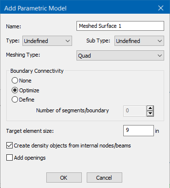
Specify the desired meshing parameters:
- Type a Name for the meshed surface. The default name is incremented.
- (Optional) Select a Type and Sub Type to identify the surface use.
- Select the Meshing Method.
- Select the Boundary Connectivity to identify the number of divisions along each surface boundary.
- Type a Target element size in the specified units of length.
- (Optional) Check the Create density objects from internal nodes/beams to generate additional nodes along any members or defined nodes that lie in the surface plane.
- (Optional) If the surface will have openings, check the Add openings option to specify those in the next dialog.
- Specify the desired meshing parameters and click OK. If you selected to add openings, the dialog to define those opens.
- (Optional)
Select an opening shape and then click OK to draw the
opening on the meshed surface.
Refer to the following tasks for additional information on adding openings.
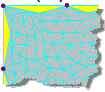
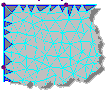
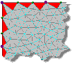
The new mesh model is displayed as an overlay on the structure with control points highlighted. The details of the mesh parameters are available in the Parametric Models dialog. - Once you are satisfied with the surface mesh, click Merge Mesh. in the Parametric Models dialog to commit it to the STAAD.Pro input file.