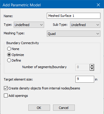
| Name
|
Type a string used to identify the meshed surface.
|
| Type
|
Select an optional description for the surface type:
|
| Sub Type
|
Select an optional description for the selected
Type:
- Wall_Tank (Wall
only)
- Slab_Tank (Slab
only)
|
| Meshing Type |
Select one of the following element shapes:
-
Quad - quadrilateral elements with four
boundary nodes
-
Triangular - triangular elements with three
boundary nodes
|
| Boundary Connectivity
|
Select how the program should sub-divide the boundary edges between the
selected nodes:
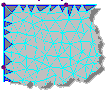
| None - Meshing will be
done without creating any nodes along the edges of the boundary
we defined. This also ignores any boundary condition (divisions
or densities) and the element size. Thus, the entire distance
between two sequential nodes will form the side of one element.
In most cases, this can lead to poor quality elements, and is
best avoided. |
No divisions
|
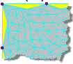
| Optimize - (Default,
recommended) Automatic boundary divisions to the target element
size. |
Optimized
|
Define - Each boundary between the selected
nodes will be sub-divided into the specified number of segments
given in Number of
segments/boundary.Note: The default
value of 0 will result in the application using the
Target element size to generate
segments along edges (sim. to the
Optimize option). A value of 1
will result in no segmentation between nodes (sim. to the
None option).
|
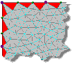
Equal number of divisions
|
|
| Target element size
|
Specify a target dimension to use as a guideline
when automatically generating the mesh. This value is nominally used when
dividing the boundary region into finite elements, but the element size is also
determined by other factors such as the distance between boundary and other
density points..
|
| Create density objects from internal nodes/beams
|
Check this option to have additional nodes created along any
members or defined nodes that lie in the defined surface area.
|
| Add openings
|
Check this option to specify openings within the surface after
you click
OK.
|
| OK
|
Closes the dialog and generates the mesh. |
| Cancel
|
Closes the dialog without generating a meshed
surface.
|