STAAD.Pro Help

EX. UK-2 Area Load Generation on Floor Structure

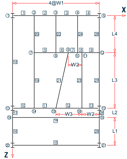
A floor structure (bound by global X-Z axis) made up of steel beams is subjected to area load (i.e., load/area of floor). Load generation based on one-way distribution is illustrated in this example.

In the case of loads such as joint loads and member loads, the magnitude and direction of the load at the applicable joints and members is directly known from the input. However, the area load is a different sort of load where a load intensity on the given area has to be converted to joint and member loads. The calculations required to perform this conversion are done only during the analysis. Consequently, the loads generated from the AREA LOAD command can be viewed only after the analysis is completed.

This problem is installed with the program by default to C:\Users\Public\Public Documents\STAAD.Pro CONNECT Edition\Samples\Sample Models\UK\UK-2 Area Load Generation on Floor Structure.STD when you install the program.

Example Problem No. 2

Where:

  • W1 = 1.5 m, W2 = 1.0 m, W3 = 1.5 m, L1 = 2.0 m, L2 = 4.5 m, L3 = 3.0 m

Actual input is shown in bold lettering followed by explanation.

   STAAD FLOOR A FLOOR FRAME DESIGN WITH AREA LOAD

Every input has to start with the term STAAD. The term FLOOR signifies that the structure is a floor structure and the structure is in the x – z plane.

   UNIT METER KNS 

Defines the input units for the data that follows.

   JOINT COORDINATES 
   1 0 0 0 5 6 0 0 ; 7 1.5 0 3 
   8 3 0 3 ; 9 4 0 3 ; 10 4.5 0 3 ; 11 5 0 3 
   12 6 0 3 ; 13 0 0 7.5 ; 14 1.5 0. 7.5
   15 3.5 0 7.5
   16 5 0 7.5 ; 17 6 0 7.5 ; 18 0 0 8.5 
   19 6 0 8.5 ; 20 0 0 10.5 ; 21 6 0 10.5 

Joint numbers followed by X, Y and Z coordinates are provided above. Since this is a floor structure, the Y coordinates are all the same (in this case, zero). Joints between 1 and 5 (i.e., 2, 3, 4) are generated in the first line of input, taking advantage of the equal spacing between the joints (refer to TR.11 Joint Coordinates Specification for more information).

Note: Semicolons (;) are used as line separators to allow for input of multiple sets of data on one line.
   MEMBER INCIDENCES 
   1 1 2 4 ; 5 7 8 9 ; 10 13 14 13 ; 14 18 19
   15 20 21 ; 16 18 20 ; 17 13 18 ; 18 1 13 
   19 7 14 ; 20 2 7 ; 21 9 15
   22 3 8 ; 23 11 16 ; 24 4 10 ; 25 19 21
   26 17 19 ; 27 12 17 ; 28 5 12 

Defines the members by the joints to which they are connected.

   MEMB PROP BRITISH
   1 TO 28 TABLE ST UB305X165X40 

Member properties are specified from the British steel table. The term ST stands for standard single section.

   * MEMBERS WITH PINNED ENDS ARE RELEASED FOR MZ
   MEMB RELEASE
   1 5 10 14 15 18 17 28 26 20 TO 24 START MZ
   4 9 13 14 15 18 16 27 25 19 21 TO 24 END MZ 

The first set of members (1 5 10 etc) have local moment-z (MZ) released at the start joint. This means that these members cannot carry any moment-z (i.e., strong axis moment) at the start joint. The second set of members have MZ released at the end joints.

Note: Any line beginning with an asterisk (* character) is treated as a comment line.
   UNIT MMS
   DEFINE MATERIAL START
   ISOTROPIC STEEL
   E 210
   POISSON 0.3
   DENSITY 7.68191e-008
   ALPHA 6e-006
   DAMP 0.03
   TYPE STEEL
   STRENGTH FY 0.24821 FU 0.399894 RY 1.5 RT 1.2
   END DEFINE MATERIAL
   UNIT METER

Define the material properties for steel. The units are changed to millimeters and then back to meters in order to facilite inputing the values in familiar units.

   CONSTANT
   MATERIAL STEEL ALL

The CONSTANT command instructs the program to use the defined steel material for all members.

   SUPPORT
   1 5 13 17 20 21 FIXED

A fixed support has been specified at the above joints.

   LOADING 1 14.5 KN/sq.m. DL+LL

Load case 1 is initiated followed by a title.

FLOOR LOAD
YRANGE -0.5 0.5 FLOAD -14.5

All members within a range of -0.5 meters to 0.5 meters in the global Y direction (which is the entire floor of this model) are subjected to an floor load of 14.5 KN/sq.m. The program converts area loads into individual member loads.

   PERFORM ANALYSIS PRINT LOAD DATA

This command instructs the program to proceed with the analysis. The PRINT LOAD DATA command is specified to obtain a listing of the member loads which were generated from the FLOOR LOAD.

   PARAMETERS
   CODE BRITISH
   BEAM 1 ALL
   DMAX 0.6 ALL
   DMIN 0.3 ALL
   UNL 0.3 ALL 

The PARAMETER command is used to specify steel design parameters (refer to D3.B.6 Design Parameters). Design is to be performed per the specifications of the BS 5950 2000 Code. The BEAM parameter is specified to perform design at every 1/12th point along the member length. DMAX and DMIN specify maximum and minimum depth limitations to be used during member selection. UNL is used to specify unsupported length of the compression flange to be used for calculation of allowable bending stress.

   SELECT MEMB 2 6 11 14 15 16 18 19 21 23 24 27

The above command instructs the program to select the most economical section from the British steel table for the members listed.

   FINISH

The FINISH command terminates the STAAD run.

Input File

STAAD FLOOR  A FLOOR FRAME DESIGN WITH AREA LOAD
UNIT METER KNS
JOINT COORDINATES
1 0. 0. 0. 5 6. 0. 0. ; 7 1.5 0. 3.
8 3. 0. 3. ; 9 4. 0. 3. ; 10 4.5 0. 3.
11 5. 0 3. ; 12 6. 0. 3. ; 13 0. 0. 7.5
14 1.5 0. 7.5 ; 15 3.5 0. 7.5
16 5. 0. 7.5 ; 17 6. 0. 7.5 18 0. 0. 8.5
19 6. 0. 8.5 ; 20 0. 0. 10.5 ; 21 6. 0. 10.5
MEMBER INCIDENCES
1 1 2 4 ; 5 7 8 9 ; 10 13 14 13 ; 14 18 19
15 20 21 ; 16 18 20 ; 17 13 18 ; 18 1 13
19 7 14 ; 20 2 7 ; 21 9 15
22 3 8 ; 23 11 16 ; 24 4 10 ; 25 19 21
26 17 19 ; 27 12 17 ; 28 5 12
MEMB PROP BRITISH
1 TO 28 TABLE ST UB305X165X40
* MEMBERS WITH PINNED ENDS ARE RELEASED FOR MZ
MEMB RELEASE
1 5 10 14 15 18 17 28 26 20 TO 24 START MZ
4 9 13 14 15 18 16 27 25 19 21 TO 24 END MZ
UNIT MMS
DEFINE MATERIAL START
ISOTROPIC STEEL
E 210
POISSON 0.3
DENSITY 7.68191e-008
ALPHA 6e-006
DAMP 0.03
TYPE STEEL
STRENGTH FY 0.24821 FU 0.399894 RY 1.5 RT 1.2
END DEFINE MATERIAL
UNIT MMS KN
CONSTANTS
MATERIAL STEEL ALL
UNIT METER KN
SUPPORT
1 5 13 17 20 21 FIXED
LOADING 1 14.5 KN/sq.m. DL+LL
FLOOR LOAD
YRANGE -0.5 0.5 FLOAD -14.5
PERFORM ANALYSIS PRINT LOAD DATA
PARAMETERS
CODE EN 1993-1-1:2005
NA 1
BEAM 3 ALL
DMAX 0.6 ALL
DMIN 0.3 ALL
UNL 0.3 ALL
SELECT MEMB 2 6 11 14 15 16 18 19 21 23 24 27
FINISH

STAAD Output File

                                                                  PAGE NO.    1
             ****************************************************        
             *                                                  *        
             *           STAAD.Pro CONNECT Edition              *        
             *           Version  22.12.00.***                  *        
             *           Proprietary Program of                 *        
             *           Bentley Systems, Inc.                  *        
             *           Date=    OCT 27, 2022                  *        
             *           Time=    15: 7:33                      *        
             *                                                  *        
             *  Licensed to: Bentley Systems Inc                *        
             ****************************************************        
     1. STAAD FLOOR  A FLOOR FRAME DESIGN WITH AREA LOAD
INPUT FILE: UK-2 Area Load Generation on Floor Structure.STD
     2. UNIT METER KNS
     3. JOINT COORDINATES
     4. 1 0. 0. 0. 5 6. 0. 0. ; 7 1.5 0. 3.
     5. 8 3. 0. 3. ; 9 4. 0. 3. ; 10 4.5 0. 3.
     6. 11 5. 0 3. ; 12 6. 0. 3. ; 13 0. 0. 7.5
     7. 14 1.5 0. 7.5 ; 15 3.5 0. 7.5
     8. 16 5. 0. 7.5 ; 17 6. 0. 7.5 18 0. 0. 8.5
     9. 19 6. 0. 8.5 ; 20 0. 0. 10.5 ; 21 6. 0. 10.5
    10. MEMBER INCIDENCES
    11. 1 1 2 4 ; 5 7 8 9 ; 10 13 14 13 ; 14 18 19
    12. 15 20 21 ; 16 18 20 ; 17 13 18 ; 18 1 13
    13. 19 7 14 ; 20 2 7 ; 21 9 15
    14. 22 3 8 ; 23 11 16 ; 24 4 10 ; 25 19 21
    15. 26 17 19 ; 27 12 17 ; 28 5 12
    16. MEMB PROP BRITISH
    17. 1 TO 28 TABLE ST UB305X165X40
    18. * MEMBERS WITH PINNED ENDS ARE RELEASED FOR MZ
    19. MEMB RELEASE
    20. 1 5 10 14 15 18 17 28 26 20 TO 24 START MZ
    21. 4 9 13 14 15 18 16 27 25 19 21 TO 24 END MZ
    22. UNIT MMS
    23. DEFINE MATERIAL START
    24. ISOTROPIC STEEL
    25. E 210
    26. POISSON 0.3
    27. DENSITY 7.68191E-008
    28. ALPHA 6E-006
    29. DAMP 0.03
    30. TYPE STEEL
    31. STRENGTH FY 0.24821 FU 0.399894 RY 1.5 RT 1.2
    32. END DEFINE MATERIAL
    33. UNIT MMS KN
    34. CONSTANTS
    35. MATERIAL STEEL ALL
    36. UNIT METER KN
    37. SUPPORT
    38. 1 5 13 17 20 21 FIXED
      A FLOOR FRAME DESIGN WITH AREA LOAD                      -- PAGE NO.    2
    39. LOADING 1 14.5 KN/SQ.M. DL+LL
    40. FLOOR LOAD
    41. YRANGE -0.5 0.5 FLOAD -14.5
 **NOTE** about Floor/OneWay Loads/Weights.
   Please note that depending on the shape of the floor you may
   have to break up the FLOOR/ONEWAY LOAD into multiple commands.
   For details please refer to Technical Reference Manual
   Section 5.32.4.2 Note d and/or "5.32.4.3 Note f.
    42. PERFORM ANALYSIS PRINT LOAD DATA
            P R O B L E M   S T A T I S T I C S
            -----------------------------------
     NUMBER OF JOINTS         20  NUMBER OF MEMBERS      28
     NUMBER OF PLATES          0  NUMBER OF SOLIDS        0
     NUMBER OF SURFACES        0  NUMBER OF SUPPORTS      6
           Using 64-bit analysis engine.
           SOLVER USED IS THE IN-CORE ADVANCED MATH SOLVER
   TOTAL      PRIMARY LOAD CASES =     1, TOTAL DEGREES OF FREEDOM =      42
   TOTAL LOAD COMBINATION  CASES =     0  SO FAR.
      A FLOOR FRAME DESIGN WITH AREA LOAD                      -- PAGE NO.    3
   LOADING     1  14.5 KN/SQ.M. DL+LL                                         
   -----------
   MEMBER LOAD - UNIT KN   METE
   MEMBER     UDL      L1     L2      CON       L     LIN1     LIN2
      1                            -0.0637 GY   0.06
      1                            -0.1912 GY   0.15
      1                            -0.3186 GY   0.24
      1                            -0.4460 GY   0.33
      1                            -0.5735 GY   0.42
      1                            -0.7009 GY   0.52
      1                            -0.8284 GY   0.61
      1                            -0.9558 GY   0.70
      1                            -0.9558 GY   0.80
      1                            -0.8284 GY   0.89
      1                            -0.7009 GY   0.98
      1                            -0.5735 GY   1.08
      1                            -0.4460 GY   1.17
      1                            -0.3186 GY   1.26
      1                            -0.1912 GY   1.35
      1                            -0.0637 GY   1.44
     20   -10.8750 GY   0.75    3.00
     20                            -0.0637 GY   0.06
     20                            -0.1912 GY   0.15
     20                            -0.3186 GY   0.24
     20                            -0.4460 GY   0.33
     20                            -0.5735 GY   0.42
     20                            -0.7009 GY   0.52
     20                            -0.8284 GY   0.61
     20                            -0.9558 GY   0.70
     19   -10.8750 GY   0.00    3.75
     19                            -0.9558 GY   3.80
     19                            -0.8284 GY   3.89
     19                            -0.7009 GY   3.98
     19                            -0.5735 GY   4.08
     19                            -0.4460 GY   4.17
     19                            -0.3186 GY   4.26
     19                            -0.1912 GY   4.35
     19                            -0.0637 GY   4.44
     10                            -0.0637 GY   0.06
     10                            -0.1912 GY   0.15
     10                            -0.3186 GY   0.24
     10                            -0.4460 GY   0.33
     10                            -0.5735 GY   0.42
     10                            -0.7009 GY   0.52
     10                            -0.8284 GY   0.61
     10                            -0.9558 GY   0.70
     10                            -0.9558 GY   0.80
     10                            -0.8284 GY   0.89
     10                            -0.7009 GY   0.98
     10                            -0.5735 GY   1.08
      A FLOOR FRAME DESIGN WITH AREA LOAD                      -- PAGE NO.    4
     10                            -0.4460 GY   1.17
     10                            -0.3186 GY   1.26
     10                            -0.1912 GY   1.35
     10                            -0.0637 GY   1.44
     18                            -0.0637 GY   0.06
     18                            -0.1912 GY   0.15
     18                            -0.3186 GY   0.24
     18                            -0.4460 GY   0.33
     18                            -0.5735 GY   0.42
     18                            -0.7009 GY   0.52
     18                            -0.8284 GY   0.61
     18                            -0.9558 GY   0.70
     18   -10.8750 GY   0.75    6.75
     18                            -0.9558 GY   6.80
     18                            -0.8284 GY   6.89
     18                            -0.7009 GY   6.98
     18                            -0.5735 GY   7.08
     18                            -0.4460 GY   7.17
     18                            -0.3186 GY   7.26
     18                            -0.1912 GY   7.35
     18                            -0.0637 GY   7.44
      2                            -0.0637 GY   0.06
      2                            -0.1912 GY   0.15
      2                            -0.3186 GY   0.24
      2                            -0.4460 GY   0.33
      2                            -0.5735 GY   0.42
      2                            -0.7009 GY   0.52
      2                            -0.8284 GY   0.61
      2                            -0.9558 GY   0.70
      2                            -0.9558 GY   0.80
      2                            -0.8284 GY   0.89
      2                            -0.7009 GY   0.98
      2                            -0.5735 GY   1.08
      2                            -0.4460 GY   1.17
      2                            -0.3186 GY   1.26
      2                            -0.1912 GY   1.35
      2                            -0.0637 GY   1.44
     22                            -0.0637 GY   0.06
     22                            -0.1912 GY   0.15
     22                            -0.3186 GY   0.24
     22                            -0.4460 GY   0.33
     22                            -0.5735 GY   0.42
     22                            -0.7009 GY   0.52
     22                            -0.8284 GY   0.61
     22                            -0.9558 GY   0.70
     22   -10.8750 GY   0.75    2.25
     22                            -0.9558 GY   2.30
     22                            -0.8284 GY   2.39
     22                            -0.7009 GY   2.48
     22                            -0.5735 GY   2.58
     22                            -0.4460 GY   2.67
     22                            -0.3186 GY   2.76
     22                            -0.1912 GY   2.85
     22                            -0.0637 GY   2.94
      5                            -0.0637 GY   0.06
      5                            -0.1912 GY   0.15
      A FLOOR FRAME DESIGN WITH AREA LOAD                      -- PAGE NO.    5
      5                            -0.3186 GY   0.24
      5                            -0.4460 GY   0.33
      5                            -0.5735 GY   0.42
      5                            -0.7009 GY   0.52
      5                            -0.8284 GY   0.61
      5                            -0.9558 GY   0.70
      5                            -0.9558 GY   0.80
      5                            -0.8284 GY   0.89
      5                            -0.7009 GY   0.98
      5                            -0.5735 GY   1.08
      5                            -0.4460 GY   1.17
      5                            -0.3186 GY   1.26
      5                            -0.1912 GY   1.35
      5                            -0.0637 GY   1.44
     20                            -0.0637 GY   0.06
     20                            -0.1912 GY   0.15
     20                            -0.3186 GY   0.24
     20                            -0.4460 GY   0.33
     20                            -0.5735 GY   0.42
     20                            -0.7009 GY   0.52
     20                            -0.8284 GY   0.61
     20                            -0.9558 GY   0.70
     20   -10.8750 GY   0.75    2.25
     20                            -0.9558 GY   2.30
     20                            -0.8284 GY   2.39
     20                            -0.7009 GY   2.48
     20                            -0.5735 GY   2.58
     20                            -0.4460 GY   2.67
     20                            -0.3186 GY   2.76
     20                            -0.1912 GY   2.85
     20                            -0.0637 GY   2.94
      3                            -0.0637 GY   0.06
      3                            -0.1912 GY   0.15
      3                            -0.3186 GY   0.24
      3                            -0.4460 GY   0.33
      3                            -0.5735 GY   0.42
      3                            -0.7009 GY   0.52
      3                            -0.8284 GY   0.61
      3                            -0.9558 GY   0.70
      3                            -0.9558 GY   0.80
      3                            -0.8284 GY   0.89
      3                            -0.7009 GY   0.98
      3                            -0.5735 GY   1.08
      3                            -0.4460 GY   1.17
      3                            -0.3186 GY   1.26
      3                            -0.1912 GY   1.35
      3                            -0.0637 GY   1.44
     24                            -0.0637 GY   0.06
     24                            -0.1912 GY   0.15
     24                            -0.3186 GY   0.24
     24                            -0.4460 GY   0.33
     24                            -0.5735 GY   0.42
     24                            -0.7009 GY   0.52
     24                            -0.8284 GY   0.61
     24                            -0.9558 GY   0.70
     24   -10.8750 GY   0.75    2.25
      A FLOOR FRAME DESIGN WITH AREA LOAD                      -- PAGE NO.    6
     24                            -0.9558 GY   2.30
     24                            -0.8284 GY   2.39
     24                            -0.7009 GY   2.48
     24                            -0.5735 GY   2.58
     24                            -0.4460 GY   2.67
     24                            -0.3186 GY   2.76
     24                            -0.1912 GY   2.85
     24                            -0.0637 GY   2.94
      7                            -0.4248 GY   0.03
      7                            -0.3682 GY   0.09
      7                            -0.3115 GY   0.16
      7                            -0.2549 GY   0.22
      7                            -0.1982 GY   0.28
      7                            -0.1416 GY   0.34
      7                            -0.0850 GY   0.40
      7                            -0.0283 GY   0.46
      6                            -0.0637 GY   0.06
      6                            -0.1912 GY   0.15
      6                            -0.3186 GY   0.24
      6                            -0.4460 GY   0.33
      6                            -0.5735 GY   0.42
      6                            -0.7009 GY   0.52
      6                            -0.8284 GY   0.61
      6                            -0.9558 GY   0.70
      6                            -0.3328 GY   0.77
      6                            -0.3186 GY   0.80
      6                            -0.3044 GY   0.83
      6                            -0.2903 GY   0.86
      6                            -0.2761 GY   0.89
      6                            -0.2620 GY   0.92
      6                            -0.2478 GY   0.95
      6                            -0.2336 GY   0.98
     22                            -0.0637 GY   0.06
     22                            -0.1912 GY   0.15
     22                            -0.3186 GY   0.24
     22                            -0.4460 GY   0.33
     22                            -0.5735 GY   0.42
     22                            -0.7009 GY   0.52
     22                            -0.8284 GY   0.61
     22                            -0.9558 GY   0.70
     22   -10.8750 GY   0.75    2.25
     22                            -0.9558 GY   2.30
     22                            -0.8284 GY   2.39
     22                            -0.7009 GY   2.48
     22                            -0.5735 GY   2.58
     22                            -0.4460 GY   2.67
     22                            -0.3186 GY   2.76
     22                            -0.1912 GY   2.85
     22                            -0.0637 GY   2.94
      4                            -0.0637 GY   0.06
      4                            -0.1912 GY   0.15
      4                            -0.3186 GY   0.24
      4                            -0.4460 GY   0.33
      4                            -0.5735 GY   0.42
      4                            -0.7009 GY   0.52
      4                            -0.8284 GY   0.61
      A FLOOR FRAME DESIGN WITH AREA LOAD                      -- PAGE NO.    7
      4                            -0.9558 GY   0.70
      4                            -0.9558 GY   0.80
      4                            -0.8284 GY   0.89
      4                            -0.7009 GY   0.98
      4                            -0.5735 GY   1.08
      4                            -0.4460 GY   1.17
      4                            -0.3186 GY   1.26
      4                            -0.1912 GY   1.35
      4                            -0.0637 GY   1.44
     28                            -0.0637 GY   0.06
     28                            -0.1912 GY   0.15
     28                            -0.3186 GY   0.24
     28                            -0.4460 GY   0.33
     28                            -0.5735 GY   0.42
     28                            -0.7009 GY   0.52
     28                            -0.8284 GY   0.61
     28                            -0.9558 GY   0.70
     28   -10.8750 GY   0.75    2.25
     28                            -0.9558 GY   2.30
     28                            -0.8284 GY   2.39
     28                            -0.7009 GY   2.48
     28                            -0.5735 GY   2.58
     28                            -0.4460 GY   2.67
     28                            -0.3186 GY   2.76
     28                            -0.1912 GY   2.85
     28                            -0.0637 GY   2.94
      9                            -0.2336 GY   0.02
      9                            -0.2478 GY   0.05
      9                            -0.2620 GY   0.08
      9                            -0.2761 GY   0.11
      9                            -0.2903 GY   0.14
      9                            -0.3044 GY   0.17
      9                            -0.3186 GY   0.20
      9                            -0.3328 GY   0.23
      9                            -0.9558 GY   0.30
      9                            -0.8284 GY   0.39
      9                            -0.7009 GY   0.48
      9                            -0.5735 GY   0.58
      9                            -0.4460 GY   0.67
      9                            -0.3186 GY   0.76
      9                            -0.1912 GY   0.85
      9                            -0.0637 GY   0.94
      8                            -0.0283 GY   0.04
      8                            -0.0850 GY   0.10
      8                            -0.1416 GY   0.16
      8                            -0.1982 GY   0.22
      8                            -0.2549 GY   0.28
      8                            -0.3115 GY   0.34
      8                            -0.3682 GY   0.41
      8                            -0.4248 GY   0.47
     24                            -0.0637 GY   0.06
     24                            -0.1912 GY   0.15
     24                            -0.3186 GY   0.24
     24                            -0.4460 GY   0.33
     24                            -0.5735 GY   0.42
     24                            -0.7009 GY   0.52
      A FLOOR FRAME DESIGN WITH AREA LOAD                      -- PAGE NO.    8
     24                            -0.8284 GY   0.61
     24                            -0.9558 GY   0.70
     24   -10.8750 GY   0.75    2.25
     24                            -0.9558 GY   2.30
     24                            -0.8284 GY   2.39
     24                            -0.7009 GY   2.48
     24                            -0.5735 GY   2.58
     24                            -0.4460 GY   2.67
     24                            -0.3186 GY   2.76
     24                            -0.1912 GY   2.85
     24                            -0.0637 GY   2.94
     21                            -0.2931 GY   0.19
     21                            -0.8794 GY   0.45
     21                            -1.4656 GY   0.73
     21                            -2.0519 GY   1.02
     21                            -2.6381 GY   1.30
     21                            -3.2244 GY   1.59
     21                            -3.8106 GY   1.88
     21                            -4.3969 GY   2.16
     21                            -4.2408 GY   2.44
     21                            -3.6754 GY   2.72
     21                            -3.1099 GY   3.00
     21                            -2.5445 GY   3.27
     21                            -1.9790 GY   3.55
     21                            -1.4136 GY   3.82
     21                            -0.8482 GY   4.10
     21                            -0.2827 GY   4.34
     11                            -0.2986 GY   0.09
     11                            -0.8958 GY   0.22
     11                            -1.4929 GY   0.36
     11                            -2.0901 GY   0.50
     11                            -2.6873 GY   0.64
     11                            -3.2845 GY   0.78
     11                            -3.8816 GY   0.92
     11                            -4.4788 GY   1.06
     11                            -3.4509 GY   1.18
     11                            -2.9908 GY   1.29
     11                            -2.5306 GY   1.40
     11                            -2.0705 GY   1.51
     11                            -1.6104 GY   1.62
     11                            -1.1503 GY   1.72
     11                            -0.6902 GY   1.83
     11                            -0.2301 GY   1.93
     19                            -0.2773 GY   0.18
     19                            -0.8318 GY   0.42
     19                            -1.3863 GY   0.69
     19                            -1.9408 GY   0.95
     19                            -2.4953 GY   1.22
     19                            -3.0499 GY   1.49
     19                            -3.6044 GY   1.76
     19                            -4.1589 GY   2.03
     19                            -4.4788 GY   2.31
     19                            -3.8816 GY   2.60
     19                            -3.2845 GY   2.89
     19                            -2.6873 GY   3.18
     19                            -2.0901 GY   3.47
      A FLOOR FRAME DESIGN WITH AREA LOAD                      -- PAGE NO.    9
     19                            -1.4929 GY   3.76
     19                            -0.8958 GY   4.05
     19                            -0.2986 GY   4.31
      6                            -2.6866 GY   0.06
      6                            -2.3284 GY   0.19
      6                            -1.9702 GY   0.31
      6                            -1.6120 GY   0.44
      6                            -1.2537 GY   0.56
      6                            -0.8955 GY   0.68
      6                            -0.5373 GY   0.81
      6                            -0.1791 GY   0.92
      5                            -0.2773 GY   0.09
      5                            -0.8318 GY   0.22
      5                            -1.3863 GY   0.36
      5                            -1.9408 GY   0.50
      5                            -2.4953 GY   0.64
      5                            -3.0499 GY   0.78
      5                            -3.6044 GY   0.92
      5                            -4.1589 GY   1.06
      5                            -1.4299 GY   1.15
      5                            -1.3808 GY   1.20
      5                            -1.3316 GY   1.25
      5                            -1.2825 GY   1.29
      5                            -1.2334 GY   1.34
      5                            -1.1842 GY   1.38
      5                            -1.1351 GY   1.43
      5                            -1.0859 GY   1.48
     23                            -0.1722 GY   0.20
     23                            -0.5166 GY   0.47
     23                            -0.8609 GY   0.76
     23                            -1.2053 GY   1.06
     23                            -1.5497 GY   1.36
     23                            -1.8941 GY   1.65
     23                            -2.2384 GY   1.95
     23                            -2.5828 GY   2.25
     23                            -2.2600 GY   2.53
     23                            -1.9586 GY   2.79
     23                            -1.6573 GY   3.05
     23                            -1.3560 GY   3.31
     23                            -1.0546 GY   3.58
     23                            -0.7533 GY   3.84
     23                            -0.4520 GY   4.09
     23                            -0.1507 GY   4.33
     12                            -0.2062 GY   0.07
     12                            -0.6185 GY   0.17
     12                            -1.0309 GY   0.27
     12                            -1.4432 GY   0.38
     12                            -1.8555 GY   0.49
     12                            -2.2679 GY   0.60
     12                            -2.6802 GY   0.71
     12                            -3.0926 GY   0.81
     12                            -2.2600 GY   0.91
     12                            -1.9586 GY   0.98
     12                            -1.6573 GY   1.06
     12                            -1.3560 GY   1.14
     12                            -1.0546 GY   1.22
      A FLOOR FRAME DESIGN WITH AREA LOAD                      -- PAGE NO.   10
     12                            -0.7533 GY   1.30
     12                            -0.4520 GY   1.38
     12                            -0.1507 GY   1.45
     21                            -0.1672 GY   0.20
     21                            -0.5016 GY   0.46
     21                            -0.8360 GY   0.74
     21                            -1.1704 GY   1.03
     21                            -1.5048 GY   1.32
     21                            -1.8392 GY   1.62
     21                            -2.1736 GY   1.91
     21                            -2.5080 GY   2.20
     21                            -2.3348 GY   2.48
     21                            -2.0235 GY   2.75
     21                            -1.7122 GY   3.02
     21                            -1.4009 GY   3.29
     21                            -1.0896 GY   3.57
     21                            -0.7783 GY   3.84
     21                            -0.4670 GY   4.10
     21                            -0.1557 GY   4.35
      8                            -1.6098 GY   0.03
      8                            -1.3951 GY   0.09
      8                            -1.1805 GY   0.16
      8                            -0.9659 GY   0.22
      8                            -0.7512 GY   0.28
      8                            -0.5366 GY   0.34
      8                            -0.3220 GY   0.40
      8                            -0.1073 GY   0.46
      7                            -0.0997 GY   0.03
      7                            -0.2991 GY   0.07
      7                            -0.4984 GY   0.12
      7                            -0.6978 GY   0.16
      7                            -0.8972 GY   0.21
      7                            -1.0966 GY   0.25
      7                            -1.2959 GY   0.30
      7                            -1.4953 GY   0.34
      7                            -0.5724 GY   0.37
      7                            -0.5571 GY   0.39
      7                            -0.5418 GY   0.41
      7                            -0.5266 GY   0.42
      7                            -0.5113 GY   0.44
      7                            -0.4961 GY   0.46
      7                            -0.4808 GY   0.47
      7                            -0.4655 GY   0.49
      9                            -0.0283 GY   0.04
      9                            -0.0850 GY   0.10
      9                            -0.1416 GY   0.16
      9                            -0.1982 GY   0.22
      9                            -0.2549 GY   0.28
      9                            -0.3115 GY   0.34
      9                            -0.3682 GY   0.41
      9                            -0.4248 GY   0.47
      9                            -0.4248 GY   0.53
      9                            -0.3682 GY   0.59
      9                            -0.3115 GY   0.66
      9                            -0.2549 GY   0.72
      9                            -0.1982 GY   0.78
      A FLOOR FRAME DESIGN WITH AREA LOAD                      -- PAGE NO.   11
      9                            -0.1416 GY   0.84
      9                            -0.0850 GY   0.90
      9                            -0.0283 GY   0.96
     27                            -0.0283 GY   0.04
     27                            -0.0850 GY   0.10
     27                            -0.1416 GY   0.16
     27                            -0.1982 GY   0.22
     27                            -0.2549 GY   0.28
     27                            -0.3115 GY   0.34
     27                            -0.3682 GY   0.41
     27                            -0.4248 GY   0.47
     27    -7.2500 GY   0.50    4.00
     27                            -0.4248 GY   4.03
     27                            -0.3682 GY   4.09
     27                            -0.3115 GY   4.16
     27                            -0.2549 GY   4.22
     27                            -0.1982 GY   4.28
     27                            -0.1416 GY   4.34
     27                            -0.0850 GY   4.40
     27                            -0.0283 GY   4.46
     13                            -0.0283 GY   0.04
     13                            -0.0850 GY   0.10
     13                            -0.1416 GY   0.16
     13                            -0.1982 GY   0.22
     13                            -0.2549 GY   0.28
     13                            -0.3115 GY   0.34
     13                            -0.3682 GY   0.41
     13                            -0.4248 GY   0.47
     13                            -0.4248 GY   0.53
     13                            -0.3682 GY   0.59
     13                            -0.3115 GY   0.66
     13                            -0.2549 GY   0.72
     13                            -0.1982 GY   0.78
     13                            -0.1416 GY   0.84
     13                            -0.0850 GY   0.90
     13                            -0.0283 GY   0.96
     23                            -0.0283 GY   0.04
     23                            -0.0850 GY   0.10
     23                            -0.1416 GY   0.16
     23                            -0.1982 GY   0.22
     23                            -0.2549 GY   0.28
     23                            -0.3115 GY   0.34
     23                            -0.3682 GY   0.41
     23                            -0.4248 GY   0.47
     23    -7.2500 GY   0.50    4.00
     23                            -0.4248 GY   4.03
     23                            -0.3682 GY   4.09
     23                            -0.3115 GY   4.16
     23                            -0.2549 GY   4.22
     23                            -0.1982 GY   4.28
     23                            -0.1416 GY   4.34
     23                            -0.0850 GY   4.40
     23                            -0.0283 GY   4.46
     26                            -0.0283 GY   0.04
     26                            -0.0850 GY   0.10
     26                            -0.1416 GY   0.16
      A FLOOR FRAME DESIGN WITH AREA LOAD                      -- PAGE NO.   12
     26                            -0.1982 GY   0.22
     26                            -0.2549 GY   0.28
     26                            -0.3115 GY   0.34
     26                            -0.3682 GY   0.41
     26                            -0.4248 GY   0.47
     26                            -0.4248 GY   0.53
     26                            -0.3682 GY   0.59
     26                            -0.3115 GY   0.66
     26                            -0.2549 GY   0.72
     26                            -0.1982 GY   0.78
     26                            -0.1416 GY   0.84
     26                            -0.0850 GY   0.90
     26                            -0.0283 GY   0.96
     14                            -0.0283 GY   0.04
     14                            -0.0850 GY   0.10
     14                            -0.1416 GY   0.16
     14                            -0.1982 GY   0.22
     14                            -0.2549 GY   0.28
     14                            -0.3115 GY   0.34
     14                            -0.3682 GY   0.41
     14                            -0.4248 GY   0.47
     14    -7.2500 GY   0.50    5.50
     14                            -0.4248 GY   5.53
     14                            -0.3682 GY   5.59
     14                            -0.3115 GY   5.66
     14                            -0.2549 GY   5.72
     14                            -0.1982 GY   5.78
     14                            -0.1416 GY   5.84
     14                            -0.0850 GY   5.90
     14                            -0.0283 GY   5.96
     17                            -0.0283 GY   0.04
     17                            -0.0850 GY   0.10
     17                            -0.1416 GY   0.16
     17                            -0.1982 GY   0.22
     17                            -0.2549 GY   0.28
     17                            -0.3115 GY   0.34
     17                            -0.3682 GY   0.41
     17                            -0.4248 GY   0.47
     17                            -0.4248 GY   0.53
     17                            -0.3682 GY   0.59
     17                            -0.3115 GY   0.66
     17                            -0.2549 GY   0.72
     17                            -0.1982 GY   0.78
     17                            -0.1416 GY   0.84
     17                            -0.0850 GY   0.90
     17                            -0.0283 GY   0.96
     13    -7.2500 GY   0.00    0.50
     13                            -0.4248 GY   0.53
     13                            -0.3682 GY   0.59
     13                            -0.3115 GY   0.66
     13                            -0.2549 GY   0.72
     13                            -0.1982 GY   0.78
     13                            -0.1416 GY   0.84
     13                            -0.0850 GY   0.90
     13                            -0.0283 GY   0.96
     10    -7.2500 GY   0.50    1.50
      A FLOOR FRAME DESIGN WITH AREA LOAD                      -- PAGE NO.   13
     10                            -0.0283 GY   0.04
     10                            -0.0850 GY   0.10
     10                            -0.1416 GY   0.16
     10                            -0.1982 GY   0.22
     10                            -0.2549 GY   0.28
     10                            -0.3115 GY   0.34
     10                            -0.3682 GY   0.41
     10                            -0.4248 GY   0.47
     11    -7.2500 GY   0.00    2.00
     12    -7.2500 GY   0.00    1.50
     14                            -0.1133 GY   0.08
     14                            -0.3398 GY   0.19
     14                            -0.5664 GY   0.32
     14                            -0.7930 GY   0.44
     14                            -1.0195 GY   0.56
     14                            -1.2461 GY   0.69
     14                            -1.4727 GY   0.81
     14                            -1.6992 GY   0.94
     14   -14.5000 GY   1.00    5.00
     14                            -1.6992 GY   5.06
     14                            -1.4727 GY   5.19
     14                            -1.2461 GY   5.31
     14                            -1.0195 GY   5.44
     14                            -0.7930 GY   5.56
     14                            -0.5664 GY   5.68
     14                            -0.3398 GY   5.81
     14                            -0.1133 GY   5.92
     25                            -0.1133 GY   0.08
     25                            -0.3398 GY   0.19
     25                            -0.5664 GY   0.32
     25                            -0.7930 GY   0.44
     25                            -1.0195 GY   0.56
     25                            -1.2461 GY   0.69
     25                            -1.4727 GY   0.81
     25                            -1.6992 GY   0.94
     25                            -1.6992 GY   1.06
     25                            -1.4727 GY   1.19
     25                            -1.2461 GY   1.31
     25                            -1.0195 GY   1.44
     25                            -0.7930 GY   1.56
     25                            -0.5664 GY   1.68
     25                            -0.3398 GY   1.81
     25                            -0.1133 GY   1.92
     15                            -0.1133 GY   0.08
     15                            -0.3398 GY   0.19
     15                            -0.5664 GY   0.32
     15                            -0.7930 GY   0.44
     15                            -1.0195 GY   0.56
     15                            -1.2461 GY   0.69
     15                            -1.4727 GY   0.81
     15                            -1.6992 GY   0.94
     15   -14.5000 GY   1.00    5.00
     15                            -1.6992 GY   5.06
     15                            -1.4727 GY   5.19
     15                            -1.2461 GY   5.31
     15                            -1.0195 GY   5.44
      A FLOOR FRAME DESIGN WITH AREA LOAD                      -- PAGE NO.   14
     15                            -0.7930 GY   5.56
     15                            -0.5664 GY   5.68
     15                            -0.3398 GY   5.81
     15                            -0.1133 GY   5.92
     16                            -0.1133 GY   0.08
     16                            -0.3398 GY   0.19
     16                            -0.5664 GY   0.32
     16                            -0.7930 GY   0.44
     16                            -1.0195 GY   0.56
     16                            -1.2461 GY   0.69
     16                            -1.4727 GY   0.81
     16                            -1.6992 GY   0.94
     16                            -1.6992 GY   1.06
     16                            -1.4727 GY   1.19
     16                            -1.2461 GY   1.31
     16                            -1.0195 GY   1.44
     16                            -0.7930 GY   1.56
     16                            -0.5664 GY   1.68
     16                            -0.3398 GY   1.81
     16                            -0.1133 GY   1.92
   ************ END OF DATA FROM INTERNAL STORAGE ************
    43. PARAMETERS
    44. CODE EN 1993-1-1:2005
    45. NA 1
    46. BEAM 3 ALL
    47. DMAX 0.6 ALL
    48. DMIN 0.3 ALL
    49. UNL 0.3 ALL
    50. SELECT MEMB 2 6 11 14 15 16 18 19 21 23 24 27
 STEEL DESIGN    
                         STAAD.PRO MEMBER SELECTION - BS EN 1993-1-1:2005
                         ********************************************
                         NATIONAL ANNEX - NA to BS EN 1993-1-1:2005
 PROGRAM CODE REVISION V1.14 BS_EC3_2005/1
      A FLOOR FRAME DESIGN WITH AREA LOAD                      -- PAGE NO.   15
 ALL UNITS ARE - KN   METE (UNLESS OTHERWISE Noted)
 MEMBER     TABLE       RESULT/   CRITICAL COND/     RATIO/     LOADING/
                          FX            MY             MZ       LOCATION
 =======================================================================
       2 ST  UB406X140X46 (BRITISH SECTIONS)
                           PASS     EC-6.2.5           0.875         1
                        0.00            0.00        -182.50        0.00
       6 ST  UB406X140X39 (BRITISH SECTIONS)
                           PASS     EC-6.2.5           0.782         1
                        0.00            0.00         133.08        1.00
      11 ST  UB457X152X52 (BRITISH SECTIONS)
                           PASS     EC-6.2.5           0.878         1
                        0.00            0.00        -226.94        1.17
      14 ST  UB305X102X33 (BRITISH SECTIONS)
                           PASS     EC-6.2.5           0.842         1
                        0.00            0.00         -95.16        3.00
      15 ST  UB305X102X25 (BRITISH SECTIONS)
                           PASS     EC-6.2.5           0.782         1
                        0.00            0.00         -62.83        3.00
      16 ST  UB305X102X25 (BRITISH SECTIONS)
                           PASS     EC-6.2.5           0.541         1
                        0.00            0.00         -43.50        0.00
      18 ST  UB305X102X25 (BRITISH SECTIONS)
                           PASS     EC-6.2.5           0.939         1
                        0.00            0.00         -75.45        3.75
      19 ST  UB457X152X60 (BRITISH SECTIONS)
                           PASS     EC-6.2.5           0.956         1
                        0.00            0.00        -289.84        0.00
      21 ST  UB305X102X25 (BRITISH SECTIONS)
                           PASS     EC-6.2.5           0.540         1
                        0.00            0.00         -43.43        2.26
      23 ST  UB305X102X25 (BRITISH SECTIONS)
                           PASS     EC-6.2.5           0.418         1
                        0.00            0.00         -33.61        2.25
      A FLOOR FRAME DESIGN WITH AREA LOAD                      -- PAGE NO.   16
 ALL UNITS ARE - KN   METE (UNLESS OTHERWISE Noted)
 MEMBER     TABLE       RESULT/   CRITICAL COND/     RATIO/     LOADING/
                          FX            MY             MZ       LOCATION
 =======================================================================
      24 ST  UB305X102X25 (BRITISH SECTIONS)
                           PASS     EC-6.2.5           0.279         1
                        0.00            0.00         -22.43        1.50
      27 ST  UB457X152X52 (BRITISH SECTIONS)
                           PASS     EC-6.2.5           0.861         1
                        0.00            0.00        -222.56        0.00
   ************** END OF TABULATED RESULT OF DESIGN **************
    51. FINISH
   ****************************************************************************
   **WARNING** SOME MEMBER SIZES HAVE CHANGED SINCE LAST ANALYSIS.
               IN THE POST PROCESSOR, MEMBER QUERIES WILL USE THE LAST
               ANALYSIS FORCES WITH THE UPDATED MEMBER SIZES.
               TO CORRECT THIS INCONSISTENCY, PLEASE DO ONE MORE ANALYSIS.
               FROM THE UPPER MENU, PRESS RESULTS, UPDATE PROPERTIES, THEN
               FILE SAVE; THEN ANALYZE AGAIN WITHOUT THE GROUP OR SELECT
               COMMANDS.
   ****************************************************************************
             *********** END OF THE STAAD.Pro RUN ***********         
               **** DATE= OCT 27,2022   TIME= 15: 7:34 ****
      A FLOOR FRAME DESIGN WITH AREA LOAD                      -- PAGE NO.   17
         ************************************************************
         *   For technical assistance on STAAD.Pro, please visit    *
         *   http://www.bentley.com/en/support/                     *
         *                                                          *
         *   Details about additional assistance from               *
         *   Bentley and Partners can be found at program menu      *
         *   Help->Technical Support                                *
         *                                                          *
         *           Copyright (c) Bentley Systems, Inc.            *
         *                http://www.bentley.com                    *
         ************************************************************