D3.B.6 Design Parameters
Available design parameters to be used in conjunction with BS5950 are listed in table 2B.1 along with their default values.
| Parameter Name | Default Value | Description |
|---|---|---|
| CODE | - |
Must be specified as BS5950 Design code to follow. See TR.48.1 Parameter Specifications. |
| AD | Depth at end/2 | Distance between the reference axis and the axis of restraint. See G.2.3 |
| BEAM | 3.0 |
Beam divisions
|
| CAN | 0 |
Deflection check method. See Note 1 below.
|
| CB | 1 |
Specifies the method used to calculate Mb.
|
| DFF | None(Mandatory for deflection check, TRACK 4.0) |
"Deflection Length" / Maxm. allowable local deflection See Note 1d below. |
| DJ1 | Start Jointof member |
Joint No. denoting starting point for calculation of "Deflection Length." See Note 1 below. |
| DJ2 | End Joint of member |
Joint No. denoting end point for calculation of "Deflection Length." See Note 1 below. |
| DMAX * | 100.0cm | Maximum allowable depth |
| DMIN * | 0.0 cm | Minimum allowable depth |
| ESTIFF | 0.0 |
Clauses 4.8.3.3.1 and 4.8.3.3.2
|
| KY | 1.0 | K factor value in local y - axis. Usually, this is the minor axis. |
| KZ | 1.0 | K factor value in local z - axis. Usually, this is the major axis. |
| LEG | 0.0 | Valid range from 0 – 7 and 10-11. The values correspond to table 25 of BS5950 for fastener conditions. See note 2 below. |
| LVV * |
Maximum of Lyy and Lzz(Lyy is a term used by BS5950) |
Used in conjunction with LEG for Lvv as per BS5950 table 25 for double angles. See Single Angle Sections. |
| LY * | Member Length | Length in local y - axis (current units) to calculate (KY)(LY)/Ryy slenderness ratio. |
| LZ * | Member Length | Length in local z - axis (current units) to calculate (KZ)(LZ)/Rzz slenderness ratio. |
| MLT | 1.0 | Equivalent moment factor for lateral torsional buckling as defined in clause 4.8.3.3.4 |
| MX | 1.0 | Equivalent moment factor for major axis flexural buckling as defined in clause 4.8.3.3.4 |
| MY | 1.0 | Equivalent moment factor for minor axis flexural buckling as defined in clause 4.8.3.3.4 |
| MYX | 1.0 | Equivalent moment factor for minor axis lateral flexural buckling as defined in clause 4.8.3.3.4 |
| NSF | 1.0 | Net section factor for tension members. |
| PNL * | 0.0 |
Transverse stiffener spacing ("a" in Annex H1) 0.0 = Infinity Any other value used in the calculations. |
| PY * | Set according to steel grade (SGR) | Design strength of steel |
| MAIN | 0.0 |
Slenderness limit for members with compression forces, effective length/ radius of gyration, for a given axis:
|
| RATIO | 1.0 | Permissible ratio of the actual capacities. |
| SAME** | 0.0 |
Controls the sections to try during a SELECT process.
|
| SBLT | 0.0 |
Identify Section type for section classification
|
| SWAY | none | Specifies a load case number to provide the sway loading forces in clause 4.8.3.3.4 (See additional notes) |
| SGR | 0.0 |
Steel Grade per BS4360
|
| TB | 0.0 |
LImit of moment capacity in Cl 4.2.5.1: 0 = Mc limit 1.5pyZ 1= Mc limit 1.2 pyZ |
| TRACK | 0.0 |
Output details
|
| UNF | 1.0 | Unsupported length factor applied to the member length for the lateral torsional-buckling effective length per section 4.3.6.7 of BS5950. |
| UNL * | Member Length | Unsupported length for calculating lateral torsional-buckling resistance moment section 4.3.6.7 of BS5950. Given in current length units. |
| WELD |
1.0 closed 2.0 open |
Weld Type
|
* current units must be considered.
**For angles, if the original section is an equal angle, then the selected section will be an equal angle and vice-versa for unequal angles.
D3.B.6.1 Notes
-
CAN, DJ1, and DJ2 – Deflection
-
When performing the deflection check, you can choose between two methods. The first method, defined by a value 0 for the CAN parameter, is based on the local displacement. Refer to TR.44 Printing Section Displacements for Members for details on local displacement.
If the CAN parameter is set to 1, the check will be based on cantilever style deflection. Let (DX1, DY1, DZ1) represent the nodal displacements (in global axes) at the node defined by DJ1 (or in the absence of DJ1, the start node of the member). Similarly, (DX2, DY2, DZ2) represent the deflection values at DJ2 or the end node of the member.
Compute Delta = SQRT((DX2 - DX1)2 + (DY2 - DY1)2 + (DZ2 - DZ1)2)
Compute Length = distance between DJ1 & DJ2 or, between start node and end node, as the case may be.
Then, if CAN is specified a value 1, dff = L/Delta
Ratio due to deflection = DFF/dff
-
If CAN = 0, deflection length is defined as the length that is used for calculation of local deflections within a member. It may be noted that for most cases the "Deflection Length" will be equal to the length of the member. However, in some situations, the "Deflection Length" may be different. A straight line joining DJ1 and DJ2 is used as the reference line from which local deflections are measured.
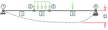
For example, refer to the figure below where a beam has been modeled using four joints and three members. The "Deflection Length" for all three members will be equal to the total length of the beam in this case. The parameters DJ1 and DJ2 should be used to model this situation. Thus, for all three members here, DJ1 should be 1 and DJ2 should be 4. D = Maximum local deflection for members 1, 2, and 3.PARAMETERS DFF 300. ALL DJ1 1 ALL DJ2 4 ALL
-
If DJ1 and DJ2 are not used, "Deflection Length" will default to the member length and local deflections will be measured from original member line.
-
It is important to note that unless a DFF value is specified, STAAD will not perform a deflection check. This is in accordance with the fact that there is no default value for DFF.
-
The above parameters may be used in conjunction with other available parameters for steel design.
-
-
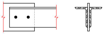
LEG – follows the requirements of BS5950 table 25. This table concerns the fastener restraint conditions for angles, double angles, tee sections, and channels for slenderness. The following values are available:
Table 2. LEG Parameter values Clause Bolt Configuration Leg LEG Parameter 4.7.10.2
Single Angle
(a) - 2 bolts short leg
1 long leg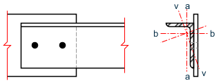
3 (b) - 1 bolts short leg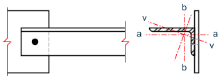
0 long leg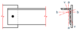
2 4.7.10.3 Double Angles (a) - 2 bolts short leg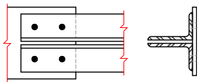
3 long leg
7 (b) - 1 bolts short leg
2 long leg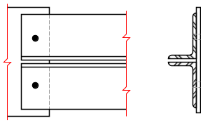
6 (c) - 2 bolts long leg 1 short leg
5 (d) - 1 bolts long leg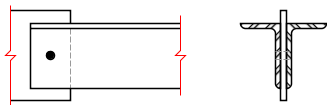
0 short leg
4 4.7.10.4 Channels (a) - 2 or more rows of bolts 
1 (b) - 1 row of bolts 
0 4.7.10.5 Tee Sections (a) - 2 or more rows of bolts 
1 (b) - 1 row of bolts 
0 The slenderness of single and double angle, channel and tee sections are specified in BS 5950 table 25 depending on the connection provided at the end of the member. To define the appropriate connection, a LEG parameter should be assigned to the member.
For single angles, the slenderness is calculated for the geometric axes, a-a and b-b as well as the weak v-v axis. The effective lengths of the geometric axes are defined as:La = KY × LY Lb = KZ × LZ The slenderness calculated for the v-v axis is then used to calculate the compression strength pc for the weaker principal axis (z-z for ST angles or y-y for RA specified angles). The maximum slenderness of the a-a and b-b axes is used to calculate the compression strength pc for the stronger principal axis.
Alternatively for single angles where the connection is not known or Table 25 is not appropriate, by setting the LEG parameter to either 10 or 11, the slenderness is calculated for the two principal axes y-y and z-z only. Use LEG 10 for the longer leg and LEG 11 for the shorter leg. The LVV parameter is not used.
For double angles, the LVV parameter is available to comply with note 5 in table 25. In addition, if using double angles from user tables, (refer to TR.19.4 Double Angle) an eleventh value, rvv, should be supplied at the end of the ten existing values corresponding to the radius of gyration of the single angle making up the pair.
-
PY – Steel Design Strength
The design parameter PY should only be used when a uniform design strength for an entire structure or a portion thereof is required. Otherwise the value of PY will be set according to the stipulations of BS5950 table 9 in which the design strength is seen as a function of cross sectional thickness for a particular steel grade (SGR parameter) and particular element considered. Generally speaking this option is not required and the program should be allowed to ascertain the appropriate value.
-
UNL, LY, and LZ – Relevant Effective Length
The values supplied for UNL, LY and LZ should be real numbers greater than zero in current units of length. They are supplied along with or instead of UNF, KY and KZ (which are factors, not lengths) to define lateral torsional buckling and compression effective lengths respectively. Please note that both UNL or UNF and LY or KY values are required even though they are often the same values. The former relates to compression flange restraint for lateral torsional buckling while the latter is the unrestrained buckling length for compression checks.
-
TRACK – Control of Output Formats
When the TRACK parameter is set to 0.0, 1.0, or 2.0, member capacities will be printed in design related output (code check or member selection) in kilonewtons per square meter.
TRACK 4.0 causes the design to carry out a deflection check, usually with a different load list to the main code check. The members that are to be checked must have the parameters DFF, DJ1, and DJ2 set.
-
MX, MY, MYX, and MLT – Equivalent Moment Factors
The values for the equivalent moment factors can either be specified directly by the user as a positive value between 0.4 and 1.0 for MX, MY and MYX and 0.44 and 1.0 for MLT.
The program can be used to calculate the values for the equivalent moment factors by defining the design member with a GROUP command (refer to TR.16.1 Listing of Entities by Specifying Groups). The nodes along the beam can then be defined as the location of restraint points with J settings.
Additionally for the MLT parameter, the joint can be defined as having the upper flange restrained (positive local Y) with the a U setting or the lower flange restrained (negative local Y) with a L setting.
For example, consider a series of 5 beam elements as a single continuous member as shown below:
To enable the steel design, the beam needs to be defined as a group, called MainBeam:
START  GROUP DEFINITION
MEMBER
_MainBeam  11 2 38 12 3
END  GROUP DEFINITION
Therefore, this 5 beam member has 6 joints such that:
- Joint 1 = Node 3
- Joint 2 = Node 1
- Joint 3 = Node 33
- Joint 4 = Node 14
- Joint 5 = Node 7
- Joint 6 = Node 2
-
Consider MX, MY and MYX
Say that this member has been restrained in its’ major axis (local Y) only at the ends. In the minor axis (local Z) it has been restrained at the ends and also at node number 33 (joint 3). For local flexural buckling, it has only been restrained at its ends. Hence:
For the major axis, local Y axis:
MX _MainBeam J1 J6
For the minor axis, local Z axis:
MY _ MainBeam J1 J3 J6
For the lateral flexural buckling, local X axis:
MYX _ MainBeam J1 J6
-
Consider MLT
Say that this member has been restrained at its’ ends against lateral torsional buckling and the top flange has been restrained at node number 33 (joint 3) and only the lower flange at node number 7, (joint 5). Hence:
MLT _MainBeam J1 T3 L5 J6
To split the beam into two buckling lengths for Ly at joint 14:
MY _groupname J1 J4 J6
-
SWAY – Sway Loadcase
This parameter is used to specify a load case that is to be treated as a sway load case in the context of clause 4.8.3.3.4. This load case would be set up to represent the kam pMs mentioned in this clause and the steel design module would add the forces from this load case to the forces of the other load case it is designed for.
Note that the load case specified with this parameter will not be designed as a separate load case. The following is the correct syntax for the parameter:
Parameter Name Default Value Description SWAY (load case number) ALL
MEMBER (member list)
_(group name)
Example
SWAY  5 MEM 1 to 10
SWAY  6 _MainBeams