TR.5 Set Command Specification
This command allows you to set various general specifications for the analysis/design run.
General Format
SET { NL i1 | {DISPLACEMENT i2 | PDELTA TOLERANCE i9} | SDAMP i3 | WARP i4 | ITERLIM i5 | PRINT i7 | NOPRINT DIRECT | SHEAR | ECHO { ON | OFF } | GUI i6 | { Z | Y } UP | DEFLECTION CUTOFF f1 | FLOOR LOAD TOLERANCE f2 | EIGEN METHOD { LANCZOS | RITZ} }
Where:
Description
The following SET commands contain values with associated units and should appear after a UNIT command and before the first JOINT command.
| Command | Parameter | Description |
|---|---|---|
| SET NL | i1 | The SET NL command is used in a multiple
analysis run if you want to add more primary load cases after one
analysis has been performed. Specifically, for those examples which
use the CHANGE command (see TR.38 Change Specification), if you want to add more primary load
cases, the NL value should be set to the maximum number (or slightly
more) with the SET NL command. The program will
then be able to set aside additional memory space for information to
be added later. This command should be provided before any joint,
member or load specifications. The value for i1 is the maximum number of primary load cases (NL). This value should not be much greater than the maximum number of primary load cases actually used in the model. |
|
SET DISPLACEMENT |
i2 | For PDELTA ANALYSIS
(refer
to TR.37.2
P-Delta Analysis Options for additional information)
The SET DISPLACEMENT i2 command is used to specify the convergence tolerance. If the Euclidean norm RMS displacement of two consecutive iterations changes less than the value entered, then that load case is converged. This command should be placed before the JOINT COORDINATE specification. The default tolerance value, i2 , is equal to the maximum span of structure divided by 120. The convergence tolerance for the Euclidean norm is difficult to know, so using this option is not recommended. i2 = If the change in the Euclidean norm of the displacement vector from one PDELTA iteration to the next is less than this convergence tolerance value; then the iteration has converged for the case being analyzed. |
| SET DEFLECTION CUTOFF | f1 | Used to arrest huge
displacements in minor axis due to small delta effects.
f1 = If the absolute value of the maximum section displacement is less than f1 after two iterations; then it is converged. Rapidly diverging minor axis displacement will not occur until after two iterations. f1 is in current length units. |
| SET FLOOR LOAD TOLERANCE | f2 |
Used to specify the tolerance for out of plane nodes in a floor load. The program expects all nodes to lie in the same plain. If there is any minor variation in coordinates of the nodes, the program will excluded floor panels connected to those nodes. Hence, a tolerance value is used to so that all nodes with in the range (min. Y and min Y + tolerance). The default is take as 0.01% of the length of the longest beam of the beams in the floor load command. Refer to TR.32.4.3 Floor Load Specification for details on specifying a plane for floor loads. f2 = the maximum distance any node can be from the plane, in the current length units |
The following SET commands have dimensionless input
| Command | Parameter | Description |
|---|---|---|
| SET SDAMP | i3 | The
SET SDAMP command will allow the damping of springs to
be considered in computing the composite modal damping for each mode in a
dynamic solution. This command is not used unless CDAMP ratios are also entered
for the members and elements in the CONSTANTS command. Composite damping is
generally only used if there are many modes in the dynamic solution and there
are a wide range of damping ratios in the springs, members, or elements.
i3 = the damping ratio to be used for all springs in computing the modal composite damping in dynamics. |
| SET WARP | i4 | The SET WARP command will allow the I section member end warping restraint to be considered in calculating the torsional stiffness rigidity. Full or partial or no warping restraint are allowed. |
| SET ITERLIM | i5 |
This command sets the maximum number of iterations in an analysis with tension/compression only members or supports. The minimum iteration limit that may be entered is 3, then max is 150. Any value higher than this will be replaced with 150. The default value used is 10. The iterative procedure may not necessarily converge. Increasing the iterations may still not lead to convergence. Therefore it is recommended that after any tension/compression analysis, the output file should be reviewed for any warnings of non-convergence. The results from a load case that has not converged should not be used, but is provided for information only. i5 = Maximum number of tension/compression iterations. |
| SET PRINT | i7 | The following values can be used
to suppress the described warnings or include the described additional results
in the output:
i7 = Used to suppress some warning messages or to include additional output. |
| SET NOPRINT DIRECT | (n/a) | Used to turn off the tau-b details in the output file when running a Direct Analysis (refer to TR.37.5 Direct Analysis). |
| SET SHEAR | (n/a) | Including this command will omit the addition of pure shear distortion stiffness terms. This is often the method used in hand calculations and allows the analysis displacement results to be checked against those calculations. |
| SET ECHO {ON | OFF} | ON | This is a switch to turn on/off any commands that follow this command from being reported in the output file to help reduce the amount of data reported. This command can be specified at any point in the file. |
| SET GUI | 0 | A flag to indicate prevent the analysis engine from producing
the results databases used by the GUI to display in the
Post-Processing workflow. This can be used in very large models
where the last action of the analysis to create the results
databases can add a significant time to the overall analysis
process.
|
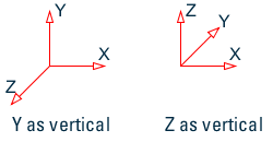
| SET { Z | Y } UP | Y UP |
Determines the axis which defines the name of the global vertical direction in the model and the name of the minor axis of beam members. It is strongly recommended to use the Y UP axis system (default) as a number of commands and methods employed in STAAD.Pro do not support the Z UP axis convention. Both options follow the "right hand rule." This command will determine the alignment of angle profiles specified with the BETA ANGLE/RANGLE specification. See section CONSTANTs specification (see TR.26 Specifying and Assigning Material Constants and G.4.2 Local Coordinate System). |
| SET STAR | i | Instructs the program which solver to use. Refer to TR.0 STAAD Commands and Input Instructions for additional
information.
|
| SET EIGEN METHOD { LANCZOS | RITZ } | (n/a) |
This command will override the default sub-space method for extracting eigen solutions as described in section G.17.3.1 Solution of the Eigenproblem. LANCZOS — Instructs the solver to use Arnoldi/Lanczos method for extraction of eigen vectors. RITZ — Use load dependent Ritz vectors method for extraction of eigen vectors. The use of either the Arnoldi/Lanczos method or the Ritz method requires a STAAD.Pro Advanced license. This command is not applicaple with the basic solver. If neither method is specified, the default method of Subspace-iteration is used. |
Less frequently used SET commands
The following table contains a list of less frequently used SET commands
| Command | Default | Description |
|---|---|---|
| SET BUCKLING MODES i | 4 | Number of buckling modes computed with advanced solver. This command is not applicable to the basic solver. |
| SET BYPASS { DIS | FOR | EJS | EJF } |
Bypass generating certain outputs for the graphical user interface.
|
|
| SET CG TXT | This command will trigger the creation of a text file (*.TXT) that includes details of the section forces for the load cases generated with a load combination command with the GENERATE optional parameter. See TR.35 Load Combination Specification for additional details. | |
| SET DIVISION i | Set the number of divisions used in meshing for surfaces (default is 10) | |
| SET ENDFACTOR f | 1.0 or -1.0 for combining spectrum cases | |
| SET GROUP DUPLICATES | Specifies the maximum number of groups any object (node, member, plate, or solid) can be included. A minimum of value 4 and a maximum of value 100. The default value is 10 groups. | |
| SET INCLINED REACTION | Used to report the reactions of inclined supports in their inclined axis system. If not specified the reactions will be in the global axis. | |
| SET INPLANE ROTATION | In-plane rotation (MX) in plates will be ignored. | |
| SET LOAD PLATE | Include loads applied to inactive plates. | |
| SET MASS i | 1 = Use generated moments as masses | |
| SET MULTI { 1 | 2 } | If multi-linear analysis fails to converge, try entering SET MULTI 2 and re-running. | |
| SET NF TXT | Used to print section forces for each member corresponding to the critical load combination generation case to an external text file. See TR.35 Load Combination Specification for additional details. This command should be used only for review of data and not in normal circumstances as the resulting text file can be very large. | |
| SET NOSECTION | This command is used to reduce the size of associated data files from the analysis. Note that this will limit the items that can be viewed in the Post Processing Workflow. Node displacements and reactions can be reported. The only diagram available will be the Deflection diagram (as this is based purely on the node displacements). Beam, plate, and sold results will not be available in tables or diagrams. However, beam end results can be included in the output file using the command PRINT MEMBER FORCES. | |
| SET NOTE { ON | OFF } | This commend toggles whether advice notes are displayed in the output file (.anl). When set to OFF the notes are not displayed. (ON is default). | |
| SET NOWARNING | Switches off some warning messages. | |
| SET PARTICIPATION FACTOR | Including this command will extend the details of a dynamic analysis to include participation factors normalised to 1.0. | |
| SET PLATE FLATNESS TOLERANCE f | 30 |
This is used to set the tolerance for determining if any four-noded plate element is out of plane. The value entered in degrees is the maximum allowable deviation of one node from a plane defined by the other three nodes. Note: It is possible to test before the analysis using the tool menu. For more information see section
M. To check for warped plates.
The value f is given in degrees. |
| SET PROFILE s2 | A command to define the path of the folder that contains
the collection of databases of section property data in SQLite
(.DB3) files. Note also that the GUI will
use this as the location of the section profile databases. The default file path used is C:\ProgramData\Bentley\Engineering\STAAD.Pro CONNECT Edition\Sections\. |
|
| SET RIGID DIAPHRAGM i | 150 | This command is used to reserve memory for the maximum number of diaphragms that may be defined in the model. See section TR.28.2 Floor Diaphragm for more information on defining and using floor diaphragms in an analysis. |
| SET RS TXT | This command will trigger the creation of a text file (*_RESP.TXT) that includes the section forces for each mode used in a response spectrum load case. See TR.35 Load Combination Specification for additional details. | |
| SET THCOPYS i |
This command is used to set the maximum number of time history forcing functions (TYPES) to which a given node degree of freedom can be subjected. The default value is 4. |
|
| SET SOLUTION INCORE | (n/a) | For some smaller models, it may be possible to use an alternative "determinant search method" which is performed in-core. However this is limited to where the problem can be solved in a single matrix block. If not, then analysis will revert to using the subspace iteration method. This command is only applicable to the basic solver. |
| SET PRINT STIFFNESS |
This command will output the assembled global stiffness matrix to the output file (*.ANL). This command is only applicable to the basic solver. The output includes the stiffness matrix from the diagonal and only includes non-zero terms (with values of 10-20 or less are assumed to be zero). See the section below on how to read this output. See Stiffness Matrix Output for details on how to interpret the stiffness matrix output. |
Stiffness Matrix Output
When the SET PRINT STIFFNESS command is used with the Basic solver, the non-zero terms for the diagonal and upper half of the stiffness matrix are reported. The following example shows the output of adding this command to the file C:\Users\Public\Public Documents\STAAD.Pro CONNECT Edition\Samples\Verification Models\03 Static Beams\BEAM01.std
  NON-ZERO STIFFNESS MATRIX VALUES, PRINTED BY ROWS FROM THE DIAGONAL.
				ROW        1  JOINT      1  DIRECTION  6
				1  1.180099515E+05       3 -1.498726372E+03       4  5.900497573E+04
				ROW        2  JOINT      2  DIRECTION  1
				2  3.172303322E+03
				ROW        3  JOINT      2  DIRECTION  2
				3  3.289796633E+01       4 -8.326259057E+02
				ROW        4  JOINT      2  DIRECTION  6
				4  1.966832440E+05
This describes position of each non-zero term in a row starting from the diagonal and then moving right. So, this matrix would be written as: