TR.32.4.2 One-way Load Specification
The One-way Load specification be applied to groups and can also use live load reduction per IBC or UBC codes.
General Format
ONEWAY LOAD (SAVE { LOAD })
YRANGE f1 f2 ONELOAD f3 (XRA f4 f5 ZRA f6 f7) { GX | GY | GZ } (TOWARDS f8) (PRINT {MEMBER | LOAD})
or
XRANGE f1 f2 ONELOAD f3 (YRA f4 f5 ZRA f6 f7) { GX | GY | GZ } (TOWARDS f8) (PRINT {MEMBER | LOAD})
or
ZRANGE f1 f2 ONELOAD f3 (XRA f4 f5 YRA f6 f7) { GX | GY | GZ } (TOWARDS f8) (PRINT {MEMBER | LOAD})
or
_FloorGroupName ONELOAD f3 { GX | GY | GZ } (INCLINED) (TOWARDS f8)
Where:
| Parameter | Description |
|---|---|
| f1 f2 | Global coordinate values to specify Y, X, or Z range. The load will be calculated for all members lying in that global plane within the first specified global coordinate range. |
| f3 | The value of the load (unit weight over square length unit). If the global direction is omitted, then this load acts parallel to the positive global Y if command begins with YRA and based on the area projected on a X-Z plane. Similarly, for commands beginning with XRA, the load acts parallel to the positive global X and based on the area projected on a Y-Z plane. Similarly, for commands beginning with ZRA, the load acts parallel to the positive global Z and based on the area projected on a X-Y plane. |
| f4-f7 | Global coordinate values to define the corner points of the area on which the specified floor load (f3) acts. If not specified, the floor load will be calculated for all members in all floors within the first specified global coordinate range. |
| GX,GY,GZ | If a Global direction is included, then the load is re-directed to act in the specified direction(s) with a magnitude of the loads which is based on the area projected on a plane as if the Global direction was omitted. The Global direction option is especially useful in mass definition. |
| FloorGroupName | See TR.16.1 Listing of Entities by Specifying Groups for the procedure for creating FLOORGROUPs. The member-list contained in this name will be the candidates that will receive the load generated from the floor pressure. |
| f8 | Defines a member onto which the loading is directed and defines the span direction for the one way loading. If the TOWARDS option is not used, the program will default to distributing a one-way load to the longest side. See Note b below for square panels. |
INCLINED - This option must be used when a ONEWAY LOAD is applied on a set of members that form a panel(s) which is inclined to the global XY, YZ, or ZX planes.
PRINT = This option is used when floor panel information printout is required. The total number of panels identified, total area of all panels and total load generated will be printed in the output file.
PRINT MEMBER = This option is used to print panel member numbers on which loads are generated along with the total number of panels identified, total area of all panels and total load generated.
PRINT LOAD = This option is used to print panel loading information. All other information available with PRINT MEMBER will also be printed in the output file.
SAVE = This option will give panel information in an external text file named (filename) _FLD.TXT. The information corresponding to PRINT MEMBER will be printed in this file.
SAVE LOAD = This option will give panel information in an external text file named (filename) _FLD.TXT. The information corresponding to PRINT LOAD will be printed in this file.
Notes
- The structure has to be modeled in such a way that the specified global axis remains perpendicular to the floor plane(s).
-
For the FLOOR LOAD specification, a two-way distribution of the load is considered. For the ONEWAY and AREA LOAD specification, a one-way action is considered. For ONE WAY loads, the program attempts to find the shorter direction within panels for load generation purposes.
In V8i SELECTseries 6 build 20.07.11.50 and later: for one-way loads applied to square panels (i.e., span direction is the same in either direction), triangular loads are generated on the members forming the four sides of the square. The intensity of the loads, which are equal for all four members, is calculated on the basis of four triangles formed by the two intersecting diagonals of the square.
Alternately, you may use the FLOOR LOAD type.
- The load per unit area may not vary for a particular panel and it is assumed to be continuous and without holes.
-
If the floor has a shape consisting of a mixture of convex and concave edges, then break up the floor load command into several parts, each for a certain region of the floor. This will force the program to localize the search for panels and the solution will be better.
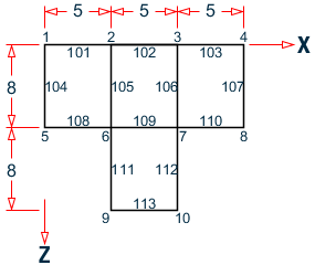
The attached example illustrates a case where the floor has to be sub-divided into smaller regions for the floor load generation to yield proper results. The internal angle at node 6 between the sides 108 and 111 exceeds 180 degrees. A similar situation exists at node 7 also. As a result, the following command:
LOAD 1
FLOOR LOAD
YRANGE 11.9 12.1 FLOAD -0.35
will not yield acceptable results. Instead, the region should be subdivided as shown in the following example
LOAD 1
FLOOR LOAD
YRANGE 11.9 12.1 FLOAD -0.35 XRA -.01 15.1 ZRA -0.1 8.1
YRANGE 11.9 12.1 FLOAD -0.35 XRA 4.9 10.1 ZRA 7.9 16.1
-
At least one quadrilateral panel bounded on at least 3 sides by "complete" members has to be present within the bounds of the user-defined range of coordinates (XRANGE, YRANGE and ZRANGE) in order for the program to successfully generate member loads from the FLOOR/ONEWAY LOAD specification. A "complete" member is defined as one whose entire length between its start and end coordinates borders the specified panel.
The load distribution pattern depends upon the shape of the panel. If the panel is Rectangular, the distribution will be Trapezoidal and triangular as explained in the following diagram.


Trapezoidal and triangular load distribution for rectangular panels
First, the CG of the polygon is calculated. Then, each corner is connected to the CG to form triangles as shown. For each triangle, a vertical line is drawn from the CG to the opposite side. If the point of intersection of the vertical line and the side falls outside the triangle, the area of that triangle will be calculated and an equivalent uniform distributed load will be applied on that side. Otherwise a triangular load will be applied on the side.
Live Load Reduction per UBC and IBC Codes
The UBC 1997, IBC 2000, and IBC 2003 codes permit reduction of floor live loads under certain situations. The provisions of these codes have been incorporated in the manner described further below.
To utilize this facility, the following conditions have to be met when creating the STAAD.Pro model.
- The live load must be applied using the FLOOR LOAD or ONEWAY LOAD option. This option is described above, and an example of its usage may be found in EX. US-15 Wind and Floor Load Generation on a Space Frame .
- As shown in TR.32 Loading Specifications, the load case has to be assigned a Type called Live at the time of creation of that case. Additionally, the option called Reducible, also has to be specified as shown.
LOAD n LOADTYPE Live REDUCIBLE
Where:
- n is the load case number
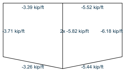
The following figures show the load generated on members for the two situations.
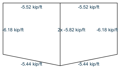
Load generated for the previously described cases
| Code Name |
Section of code which has been implemented |
Applicable Equations |
|---|---|---|
| UBC 1997 | 1607.5, page |
Equation 7-1 R = r(A-150) for FPS units R = r(A-13.94) for SI units |
| IBC 2000 | 1607.9.2, page 302 |
Equation 16-2 R = r(A-150) for FPS units R = r(A-13.94) for SI units |
| IBC 2003 | 1607.9.2, page 277 |
Equation 16-22 R = r(A-150) for FPS units R = r(A-13.94) for SI units |
| = | ||
| = | = rate of reduction equal to 0.08 for floors. |
Notes
- Only the rules for live load on Floors have been implemented. The rules for live load on Roofs have not been implemented.
- Since the medium of application of this method is the FLOOR LOAD or ONEWAY LOAD feature, and since STAAD performs load generation on beams only, the rules of the above-mentioned sections of the code for vertical members (columns) has not been implemented. The distributed load on those members found to satisfy the requirements explained in the code would have a lowered value after the reduction is applied.
- Equation (7-2) of UBC 97, (16-3) of IBC 2000 and (16-23) of IBC 2003 have not been implemented.
- In the IBC 2000 and 2003 codes, the first note says A reduction shall not be permitted in Group A occupancies. In STAAD, there is no direct method for conveying to the program that the occupancy type is Group A. So, it is the user’s responsibility to ensure that when he/she decides to utilize the live load reduction feature, the structure satisfies this requirement. If it does not, then the reduction should not be applied. STAAD does not check this condition by itself.
- In the UBC 97 code, the last paragraph of section 1607.5 states that The live load reduction shall not exceed 40 percent in garages for the storage of private pleasure cars having a capacity of not more than nine passengers per vehicle. Again, there is no method to convey to STAAD that the structure is a garage for storing private pleasure cars. Hence, it is the user’s responsibility to ensure that the structure satisfies this requirement. If it does not, then the reduction should not be applied. STAAD does not check this condition by itself.
- Because all the three codes follow the same rules for reduction, no provision is made available in the command syntax for specifying the code name according to which the reduction is to be done.