TR.25.2 Element Offset Specification
This command may be used to rigidly offset a plate element corner from a global joint to model the offset condition existing at the corners of plate elements.
General Format
- for individual joints in either local or global directions or
- offsets along the local Z axis of the element.
element-list { JT1 | JT2 | JT3 | JT4 } ( LOCAL ) f1 f2 f3
or
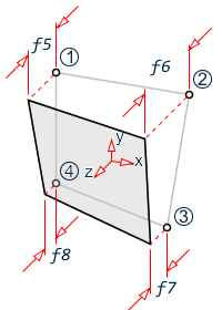
element-list ZOFF { f4 | f5 f6 f7 f8 }
where
| Parameter | Description |
|---|---|
| JT1 | JT2 | JT3 | JT4 | The element joint number based on the joint incidence for the particular element. For example, JT1 is used for the first joint specified in that element's joint incidence list. Do not use JT4 for triangular plates. |
| f1, f2, f3 | correspond to the distance, measured in local or global coordinate system, from a plate joint (JT1, JT2, JT3, or JT4 as specified) to the center plane of the associated corner point of the elements listed. |
| LOCAL | an option parameter that indicates the distances f1, f2, and f3 are in the member coordinate system with respect to the joint. If not entered, then f1, f2, and f3 are in the global coordinate system. |
| f4 | the Z offset distance to use for all four , measured in the local
coordinate system from the joint perpendicular to the surface face in the
local Z axis. This results in a constant offset of the entire element
parallel to the joints.

Constant Z offset |
| f5, f6, f7, f8 | the Z offset distance to use for each of the four joints, in order. These are measured in the local coordinate system from the joint perpendicular to the surface in the local Z axis. Do not use f8 for triangular plates. |

Description
This command can be used for any element whose corner points are not concurrent with the given incident joint. This command enables you to account for the secondary forces which are induced due to the eccentricity of the element. Element offsets can be specified in any direction, including the direction that may coincide with the element in-plane axes.
- If an element load (see TR.32.3 Element Load Specifications) is applied on an element for which element offsets have been specified, then the location of the load is measured from the offset corner locations rather than the coordinates of the global joints.
- Plate offsets are not applicable for steady state, geometric nonlinear, buckling, cable, or imperfection analysis types. An error message is generated if they are used with any of these analyses. Plate offsets are also not applicable for pushover analysis, as no elements (surface, plate, or solid) may be used with that analysis type.
- The plate area, the warped element checks, and local element coordinates are based on the offset coordinates of the corner points.
- Plate offsets are ignored static seismic loads.
- Plate offsets are ignored for joint loads, since these are not applies to plates.
- For floor diaphragms, use the SET MASS 1 command to ensure that the plate offsets are considered during the center of mass calculations. Otherwise, the plate offsets will be ignored for this calculation. The mass modeling must be done using a SET Y UP command.
Examples
The following code example demonstrates from usage of this specification.
ELEMENT OFFSET
* All 4 joints of plate 1 are offset by 7 units in the local z direction.
1 ZOFF 7

* All 4 joins of plate 2 are offset by the units specified in the local z
* direction, in the order of the joint incidience.
2 ZOFF 7 7.5 7 7.5

* The first joint in the incidence of plate 3 is offset by 7 units in the
* local z direction.
3 JT1 LOCAL 0 0 7

* The second joint int he incidence of plate 4 is offset by 7.5 units in
* the global X direction.
4 JT2 7.5 0 0
Examples of Constant Offsets
The following offset methods all give the same results for element number 1:
Example of uniform offsets for an element using different methods
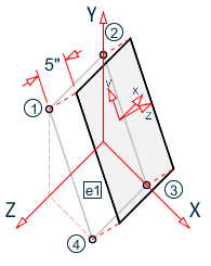
UNIT INCH
JOINT COORDINATES
1 0 20 20
2 0 20 0
3 15 0 0
4 15 0 20
…
ELEMENT INCIDENCES
1 1 2 3 4
…
ELEMENT OFFSETS
* 1) Using global coordinates at each joint
1 JT1 3 4 0
1 JT2 3 4 0
1 JT3 3 4 0
1 JT4 3 4 0

* 2) Using local coordinates at each joint
1 JT1 LOCAL 0 0 5
1 JT2 LOCAL 0 0 5
1 JT3 LOCAL 0 0 5
1 JT4 LOCAL 0 0 5

* 3) Using a single Z offset
1 ZOFF 5

* 4) Using the same Z offset at each corner
1 ZOFF 5 5 5 5
Example of Physical Modeling Offset
The following example shows how element offsets can be used to model the "real world" physical properties of how concrete walls intersect with relation to the analytical model meshing centerlines. The adjoining wall on the right side has offsets from the analytical nodes of the elements (n1, n2) to the WP at the top and bottom of the wall intersection.

UNIT INCH
ELEMENT OFFSETS
1 JT1 LOCAL 6 0 -4
1 JT2 LOCAL 6 0 -4