V. Element Offset Table Top Comparison
A simple table-like structure is composed of four column members and a single plate element. Verify that the element offset command gives similar results as those from other modeling methods.
Problem
The plate element is subjected to a pressure load acting vertically downward along global Y direction of 1 kN/m2. Also, two concentrated point loads of 10 kN are acting laterally along global X & global Z directions at center of the plate element.
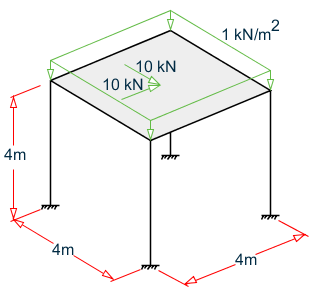
- Slab thickness = 20 cm
- Columns and beams = 40 cm square
- Concrete materials for all members and elements*
Offset the slab edge by 1/2 the column width (20 cm) in the plan dimensions and 1/2 the slab depth (10 cm) into the thickness of the slab.
Calculations
The model is generated with three different approaches to include the offset effect on the plate. First approach is to use ELEMENT OFFSET command wherein offset distances are directly assigned to corner joints of the plate without any need to manually compute co-ordinates for offset joints.

The second approach is to use control-dependent specification instead of offset commands with rigid connections between offset joints of the plate & beam-column junction for load transfer. The third approach is to use short, relatively stiff beam members (*assigned with material STIFF having high E & G values) instead of control-dependent specification so that offset joints of plate and beam-column junction are rigidly connected to ensure load transfer.

- Using element offsets in the global direction (nodes 101, 102, 103, etc.)
- Using rigid links with a high stiffness value (nodes 201, 202, 203, etc.)
- Using a control / dependent specification (nodes 301, 302, 303, etc.)
Additional node numbers added for different approaches
Comparison
Results for the model created with element offset command should be identical with the model created with control-dependent approach or short rigid beam approach. Hence, the results from control-dependent and short rigid beam models are treated as reference values against which results from model with element offset command are compared.
| Result Type | Modeling Method | Difference | |||
|---|---|---|---|---|---|
| Element Offsets | Rigid Links | Control / Dependent | |||
| Joint deflection (cm) | Joint 2, X | 0.0372 | 0.0372 | 0.0372 | none |
| Joint 2, Y | 0.0002 | 0.0002 | 0.0002 | none | |
| Joint 2, Z | 0.0372 | 0.0372 | 0.0375 | none | |
| Joint 7, X | 0.0373 | 0.0373 | 0.0373 | none | |
| Joint 7, Y | -0.0009 | -0.0009 | -0.0009 | none | |
| Joint 7, Z | 0.0373 | 0.0373 | 0.0373 | none | |
| Support Reactions | Joint 8, FX (kN) | -2.82 | -2.82 | -2.82 | none |
| Joint 8, FY (kN) | 8.05 | 8.05 | 8.05 | none | |
| Joint 8, FZ (kN) | -2.82 | -2.82 | -2.82 | none | |
| Joint 8, MX (kN·m) | -5.87 | -5.87 | -5.87 | none | |
| Joint 8, MZ | 5.87 | 5.87 | 5.87 | none | |
STAAD Input
The file C:\Users\Public\Public Documents\STAAD.Pro CONNECT Edition\Samples\ Verification Models\04 Plates Shells\Element Offset Table Top Comparison.STD is typically installed with the program.
STAAD SPACE
START JOB INFORMATION
ENGINEER DATE 16-DEC-20
END JOB INFORMATION
INPUT WIDTH 79
UNIT METER KN
JOINT COORDINATES
101 0 0 0; 102 0 4 0; 103 4 4 0; 104 4 0 0; 105 0 0 4; 106 0 4 4; 107 4 4 4;
108 4 0 4; 201 0 0 10; 202 0 4 10; 203 4 4 10; 204 4 0 10; 205 0 0 14;
206 0 4 14; 207 4 4 14; 208 4 0 14; 209 0.2 4.1 10.2; 210 3.8 4.1 10.2;
211 0.2 4.1 13.8; 212 3.8 4.1 13.8; 301 0 0 20; 302 0 4 20; 303 4 4 20;
304 4 0 20; 305 0 0 24; 306 0 4 24; 307 4 4 24; 308 4 0 24; 309 0.2 4.1 20.2;
310 3.8 4.1 20.2; 311 0.2 4.1 23.8; 312 3.8 4.1 23.8;
*Coordinates for Structure 1: Using ELEMENT OFFSETS
*Coordinates for structure 2: Using rigid, linking members
*Coordinates for structure 3: Using master/slave links
MEMBER INCIDENCES
101 101 102; 102 103 104; 103 105 106; 104 107 108; 105 102 103; 106 103 107;
107 107 106; 108 106 102; 201 201 202; 202 203 204; 203 205 206; 204 207 208;
205 202 203; 206 203 207; 207 207 206; 208 206 202; 210 202 209; 211 203 210;
212 207 212; 213 206 211; 301 301 302; 302 303 304; 303 305 306; 304 307 308;
305 302 303; 306 303 307; 307 307 306; 308 306 302;
*Structure 1
*Structure 2
*Structure 3
* 310 302 309; 311 303 310; 312 307 312; 313 306 311;
ELEMENT INCIDENCES SHELL
109 102 103 107 106; 209 209 210 212 211; 309 309 310 312 311;
*Structure 1
*Structure 2
*Structure 3
ELEMENT PROPERTY
109 209 309 THICKNESS 0.2
DEFINE MATERIAL START
ISOTROPIC CONCRETE
E 2.17185e+07
POISSON 0.17
DENSITY 23.5616
ALPHA 1e-05
DAMP 0.05
G 9.28139e+06
TYPE CONCRETE
STRENGTH FCU 27579
ISOTROPIC STIFF
E 1e+14
POISSON 0.17
DENSITY 0.0001
G 5e+13
END DEFINE MATERIAL
MEMBER PROPERTY
101 TO 108 PRIS YD 0.4 ZD 0.4
201 TO 208 PRIS YD 0.4 ZD 0.4
210 TO 213 PRIS YD 0.4 ZD 0.4
301 TO 308 PRIS YD 0.4 ZD 0.4
CONSTANTS
MATERIAL CONCRETE MEMB 101 TO 109 201 TO 209 301 TO 309
*A material with very high E and G is used for rigid links structure 2
MATERIAL STIFF MEMB 210 TO 213
ELEMENT OFFSET
***Global Offsets for structure 1
109 JT1 0.2 0.1 0.2
109 JT2 -0.2 0.1 0.2
109 JT3 -0.2 0.1 -0.2
109 JT4 0.2 0.1 -0.2
***Local Offset: an alternate method of specifying the same resulting offset
*9 JT1 LOCAL 0.2 0.2 -0.1
*9 JT2 LOCAL -0.2 0.2 -0.1
*9 JT3 LOCAL -0.2 -0.2 -0.1
*9 JT4 LOCAL 0.2 -0.2 -0.1
SUPPORTS
101 104 105 108 FIXED
201 204 205 208 FIXED
301 304 305 308 FIXED
* Master / slave specification for structure 3
DEPENDENT RIGID CONTROL 302 JOINT 309
DEPENDENT RIGID CONTROL 303 JOINT 310
DEPENDENT RIGID CONTROL 306 JOINT 311
DEPENDENT RIGID CONTROL 307 JOINT 312
LOAD 1 LOADTYPE None  TITLE LOAD CASE 1
* The elements in each of the models is loaded identically
ELEMENT LOAD
109 209 309 PR GY -1
109 209 309 PR GX 10 0 0
109 209 309 PR GZ 10 0 0
PERFORM ANALYSIS PRINT ALL
PRINT ANALYSIS RESULTS
PRINT ELEMENT JOINT STRESSES
PRINT ELEMENT FORCE
FINISH
STAAD Output
   JOINT DISPLACEMENT (CM   RADIANS)    STRUCTURE TYPE = SPACE
   ------------------
 JOINT  LOAD   X-TRANS   Y-TRANS   Z-TRANS   X-ROTAN   Y-ROTAN   Z-ROTAN
    101    1     0.0000    0.0000    0.0000    0.0000    0.0000    0.0000
    102    1     0.0372    0.0002    0.0372    0.0000    0.0000   -0.0000
    103    1     0.0372   -0.0004    0.0371    0.0001   -0.0000   -0.0000
    104    1     0.0000    0.0000    0.0000    0.0000    0.0000    0.0000
    105    1     0.0000    0.0000    0.0000    0.0000    0.0000    0.0000
    106    1     0.0371   -0.0004    0.0372    0.0000    0.0000   -0.0001
    107    1     0.0373   -0.0009    0.0373    0.0000    0.0000   -0.0000
    108    1     0.0000    0.0000    0.0000    0.0000    0.0000    0.0000
    201    1     0.0000    0.0000    0.0000    0.0000    0.0000    0.0000
    202    1     0.0372    0.0002    0.0372    0.0000    0.0000   -0.0000
    203    1     0.0372   -0.0004    0.0371    0.0001   -0.0000   -0.0000
    204    1     0.0000    0.0000    0.0000    0.0000    0.0000    0.0000
    205    1     0.0000    0.0000    0.0000    0.0000    0.0000    0.0000
    206    1     0.0371   -0.0004    0.0372    0.0000    0.0000   -0.0001
    207    1     0.0373   -0.0009    0.0373    0.0000    0.0000   -0.0000
    208    1     0.0000    0.0000    0.0000    0.0000    0.0000    0.0000
    209    1     0.0375   -0.0011    0.0375    0.0000    0.0000   -0.0000
    210    1     0.0376   -0.0006    0.0376    0.0001   -0.0000   -0.0000
    211    1     0.0376   -0.0006    0.0376    0.0000    0.0000   -0.0001
    212    1     0.0375   -0.0001    0.0375    0.0000    0.0000   -0.0000
    301    1     0.0000    0.0000    0.0000    0.0000    0.0000    0.0000
    302    1     0.0372    0.0002    0.0372    0.0000    0.0000   -0.0000
    303    1     0.0372   -0.0004    0.0371    0.0001   -0.0000   -0.0000
    304    1     0.0000    0.0000    0.0000    0.0000    0.0000    0.0000
    305    1     0.0000    0.0000    0.0000    0.0000    0.0000    0.0000
    306    1     0.0371   -0.0004    0.0372    0.0000    0.0000   -0.0001
    307    1     0.0373   -0.0009    0.0373    0.0000    0.0000   -0.0000
    308    1     0.0000    0.0000    0.0000    0.0000    0.0000    0.0000
    309    1     0.0375   -0.0011    0.0375    0.0000    0.0000   -0.0000
    310    1     0.0376   -0.0006    0.0376    0.0001   -0.0000   -0.0000
    311    1     0.0376   -0.0006    0.0376    0.0000    0.0000   -0.0001
    312    1     0.0375   -0.0001    0.0375    0.0000    0.0000   -0.0000
      STAAD SPACE                                              -- PAGE NO.    8
   SUPPORT REACTIONS -UNIT KN   METE    STRUCTURE TYPE = SPACE
   -----------------
 JOINT  LOAD   FORCE-X   FORCE-Y   FORCE-Z     MOM-X     MOM-Y     MOM Z
    101    1     -2.60     -1.57     -2.60     -5.57      0.00      5.57
    104    1     -2.40      3.24     -2.18     -5.01      0.00      5.31
    105    1     -2.18      3.24     -2.40     -5.31     -0.00      5.01
    108    1     -2.82      8.05     -2.82     -5.87      0.00      5.87
    201    1     -2.60     -1.57     -2.60     -5.57      0.00      5.57
    204    1     -2.40      3.24     -2.18     -5.01      0.00      5.31
    205    1     -2.18      3.24     -2.40     -5.31     -0.00      5.01
    208    1     -2.82      8.05     -2.82     -5.87      0.00      5.87
    301    1     -2.60     -1.57     -2.60     -5.57      0.00      5.57
    304    1     -2.40      3.24     -2.18     -5.01      0.00      5.31
    305    1     -2.18      3.24     -2.40     -5.31     -0.00      5.01
    308    1     -2.82      8.05     -2.82     -5.87      0.00      5.87