T.2 Creating Load Cases 1, 2, and 3
The load values are listed in the beginning of this tutorial in kg and meter units. Rather than convert those values to the current input units, we will conform to those units.
STAAD.Pro does not allow to change the units while editing load cases. An error message is displayed if this is attempted.
-
Change the force unit to
Kilogram and the length unit to
Meter.
Refer to T.2 Changing the input units of length for details.
-
On the
Loading ribbon tab, select the
Primary Load Case in the
Loading Specifications group.

-
Enter the properties for the first load case:
-
Type
DEAD LOAD in the
Title field.
Leave the Number as the default value of 1.
Note: The Loading Type list is used to associate the load case we are creating with any of the ACI, AISC, IBC, or other code-prescribed definitions of Dead, Live, Ice, etc. This type of association needs to be done if you intend to use the program's automatically generating load combinations in accordance with those codes. Note that there is a check box labeled Reducible per UBC/IBC. This feature is active only when the load case is assigned a Loading Type called Live when you create that load case.Since this tutorial does not use the automatic load combination generation feature, leave the Loading Type as None.
- Click Add.
- Click Close.
-
Type
DEAD LOAD in the
Title field.
- To create the selfweight dead load, either: The Add New Load Items dialog opens with entries for adding load items to the selected load case.
- Define the selfweight load:
- With the Add New Load Items dialog still open, add the member loads to be applied to the beams:
- Assign the selfweight load to all members:
-
Assign the member load to members 2 and 5:
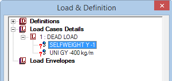
- Select the UNI GY -400 kg/m entry in the Load & Definitions dialog.
-
Press and hold <Ctrl> and then select members 2 and 5
in the View window.
The Beams Cursor tool
 is automatically
selected when the
Load & Definition dialog
is opened.
is automatically
selected when the
Load & Definition dialog
is opened.
- Select the Assign to Selected Beams option.
-
Click
Assign.
A message box opens to opens prompting you to confirm you want to make this assignment.
- Click Yes.
- Repeat steps 3, 4, 6, and 8 to create a new load case titled Live Load which contains a uniform force of -600 kg/m in the global Y direction and is applied to members 2 and 5.
-
Repeat steps 3 through 4 and then 6 through 8 to create a new load
case titled
Wind Load which contains the following two
load items:
Note: Be sure to select the Wind Load on the Loading ribbon tab Display group to add load items to this load case.
- a uniform force of +300 kg/m in the GX (global X) direction and is applied to member 1
- a uniform force of +500 kg/m in the GX (global X) direction and is applied to member 4