D3.B.1 General
The design philosophy embodied in BS5950:2000 is built around the concept of limit state design, used today in most modern steel design codes. Structures are designed and proportioned taking into consideration the limit states at which they become unfit for their intended use.
Two major categories of limit state are recognized - serviceability and ultimate. The primary considerations in ultimate limit state design are strength and stability while that in serviceability limit state is deflection. Appropriate safety factors are used so that the chances of limits being surpassed are acceptably remote.
In the STAAD.Pro implementation of BS5950:2000, members are proportioned to resist the design loads without exceeding the limit states of strength and stability. Accordingly, the most economic section is selected on the basis of the least weight criteria. This procedure is controlled by the designer in specification of allowable member depths, desired section type or other such parameters. The code checking portion of the program checks that code requirements for each selected section are met and identifies the governing criteria.
The complete B.S.C. steel tables for both hot rolled and hollow sections are built into the program for use in specifying member properties as well as for the actual design process. See D3.B.4 Built-In Steel Section Library for information regarding the referencing of these sections. In addition to universal beams, columns, joists, piles, channels, tees, composite sections, beams with cover plates, pipes, tubes, and angles, there is a provision for user provided tables.
The program designs tapered I shaped beams according to Annex G of BS5950. See D3.B.13 Design of Tapered Beams for a complete description.
Single Angle Sections
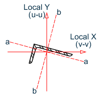
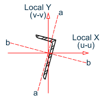
Angle sections are unsymmetric and when using BS 5950:2000 table 25, you must consider four axes: two principal, u-u and v-v and two geometric, a-a and b-b. The effective length for the v-v axis, Lvv, is taken as the LVV parameter or LY · KY, if not specified. The a-a and b-b axes are determined by which leg of the angle is fixed by the connection and should be specified using the LEG parameter, see section 5B.6 for more information on the LEG parameter. The effective length in the a-a axis is taken as LY · KY and the effective length in the b-b axis as LZ · KZ.
The following diagram shows the axes for angles which have been defined with either an ST or RA specification and is connected by its longer leg (i.e., a-a axis is parallel to the longer leg).