Isolated (Spread) Footing Theory
-
Determine footing plan geometry based on loading and bearing resistance of the soil.
Self weight of footing, self weight of pedestal is automatically considered in foundation design. The final thickness of the footing is considered for the design self weight. Soil self weight, overburden pressure, buoyancy effect is calculated based on user input specified in design parameters.
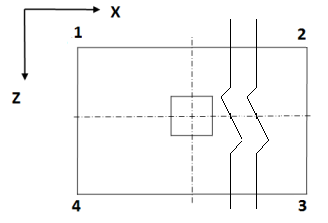
Stress distribution under the footing is assumed to be linear. The average corner pressure is taken as the algebraic average of the pressures at corners 1 through 4, as labeled in the following figure. For eccentrically loaded footings, the stresses may become tensile under part of the foundation. In such cases the program sets stress values in uplift zones to zero and calculates new values elsewhere for the revised equilibrium condition.
The program is also capable of handle biaxial moments for footings subjected to uplift (see the following section).
The program checks the footing for sliding and overturning in both orthogonal directions for all service load cases. Coefficient of friction is used to calculate sliding resistance. Passive pressure resistance for sliding will be considered in future versions.
The final plan dimensions of the footing are established iteratively from the condition that the maximum stress should not exceed the factored bearing resistance of the soil and foundation should be stable in sliding and overturning.
See the section below for a description of how the effective depth is calculated by the program.
-
Development length is checked for straight rebar. If development criterion is not met by the footing geometry a warning message is displayed in the calculation sheet, user can go for other detailing options like bent bars. Future release of STAAD Foundation Advanced will take bent up bars into consideration.
-
Calculate footing thickness based on structural capacity in shear and bending.
Structural design of the footing consists of the following:
- Punching shear check, in accordance with ACI 318 Section 11.12.2 (for US Job).
- One-way shear (beam action), in accordance with ACI 318 Section 11.1 through 11.5 (for US Job), at a distance of d from the face of the pedestal, in both orthogonal directions. The critical plane is assumed to extend over the entire width/length of the footing.
- Bending, in accordance with Sections 15.4.2 and 10.3.4 (for US code), with the critical planes located at both orthogonal faces of the pedestal and extending across the full width/length of the footing.
- Design output displays applicable code sections used for foundation design for all codes.
-
Eccentricity in both direction (X & Z, +ve as well as – ve) is considered for isolated footing.
- If the footing thickness is revised at any step while the concrete checks are being performed, the program recalculates service checks (Soil Bearing and Stability checks) with the revised thickness.
Effective Depth
For computing the flexural capacity for longitudinal and transverse bending, the effective depth is computed to the center of gravity of the upper layer of reinforcement provided at the bottom of the footing.
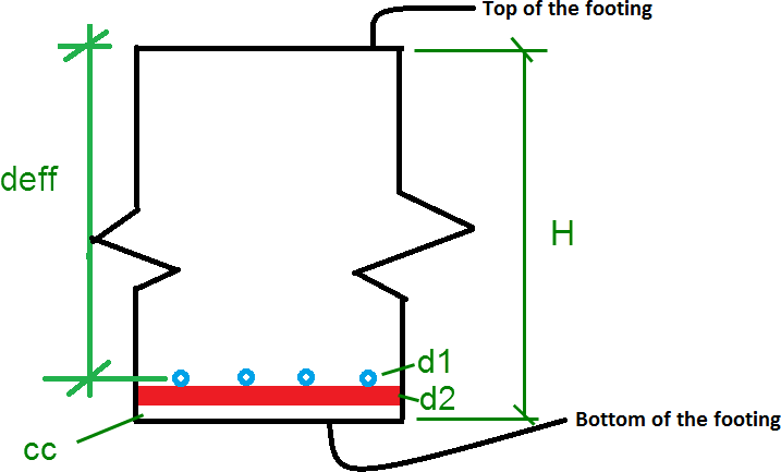
| deff = H - cc - d2 - d1/2 |
| = | ||
| = | ||
| = | ||
| = | ||
| = |
Biaxial Moment Distribution
The program uses Finite Differential Method to calculate resultant eccentricity and calculates soil pressure based on:
Punching Shear
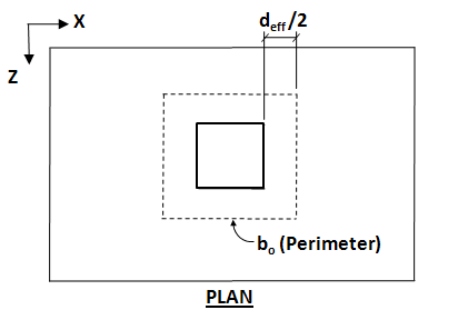
For all codes except Eurocode (EC2), the tributary area used for punching shear is taken a distance of d/2 from the pedestal (refer to the following figure). The critical section comprises four straight-line segments, parallel to the corresponding sides of the pedestal.
When expressed in equation form, this is:
Length of Footing × Width of Footing – ( Length of Column + effective depth) × ( Width of Column + effective depth)
Punching shear checks for Eurocode is performed at a distance 2d from the face of the column, as discussed in section 6.4.2 of Eurocode EC2. The shape of the punching shear perimeter is as shown in figure 6.13 of the Eurocode, which is reproduced below.

Factors of Safety in Sliding
The factor of safety in sliding is calculated only for load cases classified as "service" type.
- Disturbing force acting purely in the X direction – This is equal to the FX force specified in the service load case under consideration
- Disturbing force acting purely in the Z direction – This is equal to the FZ force specified in the service load case under consideration
- Disturbing force that is the resultant of a and b – for the service load case under consideration
- Restoring force –
(A + B + C + D - E) × μ
where
- A
= - weight of the footing concrete pad
- B
= - weight of pedestal (if any)
- C
= - weigh of soil above the footing
- D
= - FY force acting on the footing from the column above for that load case
- E
= - buoyant force due to water table = Plan area of footing × height of water above base of footing × density of water
- μ
= - coefficient of friction
- the load case considered governing for each of them respectively
- the value of the disturbing force
- the value of the restoring force
- the factor of safety
Factors of Safety in Overturning
The procedure for overturning is similar to that for sliding with a few differences.
In items (a), (b), (c) and (d), the program uses moments –MX instead of FX, MZ instead of FZ– and the restoring moment is computed about the one edge of the foundation.
MX and MZ get their contributions from those values coming from the columns, plus, the moment caused by FZ and FX respectively acting at the top of the pedestal. If there is no pedestal, FX and FZ are assumed to act at the top of the footing.