RAM Foundation
This section illustrates the analysis and design of the spread footings and continuous foundations in an integrated model. This section can only be completed if you have licensed and installed the RAM Foundation module. You may begin with the model that you generated in the previous portions of this tutorial, or you may open the model called RAMTutorial_v14_US.rss from the RAM Manager.
RAM Foundation Basics
To invoke RAM Foundation from the RAM Manager:
Because RAM Foundation is integrated into the RAM Structural System, it uses the same model and database as RAM Frame and RAM Steel when designing foundations. In order for the program to design the foundations, the loads must be determined by running the gravity column design and/or lateral analysis in RAM Frame. If this has not been done, do so now, then proceed with this Tutorial. While most of the information needed for foundation design is taken from the database, some data does need to be entered in the Foundation program itself.
Before foundations can be designed, the following must be defined:
- Soil Capacity
- Base plate size for lateral steel columns.
- Width for Continuous foundations.
- At least one load combination for Concrete.
- At least one load combination for Soil.
- Pile capacity information and layout.
Once this is complete, a design can be performed, but we recommend that you review the design and optimization criteria closely first.
To establish the source for the design loads:

Leave the Forces on Gravity Members criteria set to use the third option: RAM Steel for steel members and RAM Concrete for concrete members.
Since this model has 2 way decks RAM Steel cannot account for the loads on members underneath those decks. This is why the first option is grayed out.
To set the design criteria:
These parameters have a significant effect on the way the foundations are designed. For a complete description of the option see the RAM Foundation manual. For this example:
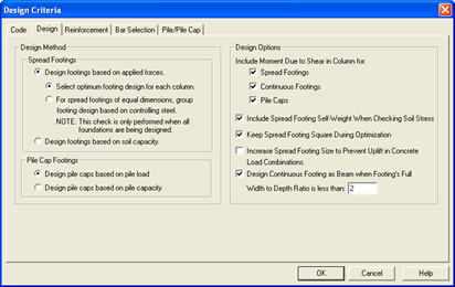
Under Design Method:
- Check all three footings for Include Moments Due to Shear in Column for:
- Check: Include Spread Footing Self-Weight When Checking Soil Stress.
- Check: Keep Spread Footing Square During Optimization.
- Uncheck to Increase Spread Footing Size to Prevent Uplift in Concrete Load Combinations.
- Check to Design Continuous Footing as Beam when Footing’s Full Width to Depth Ratio is less than.
- Enter 2 for the ratio.
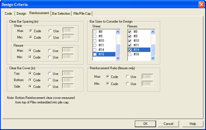
- Click on the Reinforcement tab
- Set the Clear Bar Spacing, Clear Bar Cover and Reinforcement Ratios to Code (as shown above)
- For Bars Sizes to Consider for Design, select
- Shear: #3 and #4 bars (F08 and F10)
- Flexure: #4 through #14 (F10-F20).
- Click [OK].