Span segment properties
The following is an explanation of RAM Concept span segment properties:
General tab

| Setting | Description |
|---|---|
| Span Set | Determines the set the span segment belongs to: latitude or longitude. |
| Environment |
The environment setting affects which service rules RAM Concept selects in some codes. Refer to the appropriate code discussion chapter for
more information:
|
| Consider Axial Force in Strength Design |
Uses the net section axial force in bending design. This is a very important setting related to the effect of axial force resultants (not necessarily axial loads) in a cross section. If you select this option, RAM Concept includes the interaction of the axial force with the bending in the cross section strain calculations, similar to typical column design using strain compatibility. We generally recommend the consideration of axial forces in strength design. For sections with net axial compression this will tend to reduce the reinforcement demand while for sections with net axial tension it will typically increase the reinforcement demand. |
| Ignore Size Effect Factor (for Shear in Foundations) |
This option is only be visible when ACI 318-19 is the active Design Code. It is checked by default in new models that are created when Mat Foundation is selected for Structure Type. The intent of this option is to ignore the size effect factor when designing foundation members as permitted by ACI 318-19 13.2.6.2. |
| Don't reduce integrated M and V due to sign change | The intent of this option is to allow for safe, conservative designs where
cross sections include regions of moment (or shear) with opposite signs that
cause the moment (or shear) recorded for the cross section to be less than
that for a shorter sub- cross section. When this option is selected, the design forces are always more conservative than when the option is not selected. This option should not be used without due consideration. See Using the Don't Reduce Integrated M and V due to Sign Change option for explanation. |
| Consider as Post-Tensioned |
Enables RAM Concept to decide which code rules are used. This determines if the design strip segment is checked for initial service design code rules (for the Initial Service LC) and whether RC or PT code rules are used (some codes do not make this distinction). |
| Precompression Calc |
Determines how precompression is calculated and used to plot Section Analysis results on the User Minimum Layer. See also Creating a new precompression plan. The choices are:
|
| Number of Stories for Accident Design (Eurocode 2 UK NA only) | This input will only be visible when the Eurocode 2-2004 (UK Annex) is the active Design Code. It is used to determine the number of stories that are used for accident rule set calculations for this span. |
Strip Generation tab

Column Strip tab
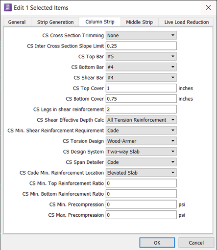
| Setting | Description | |
|---|---|---|
| Cross Section Trimming | Reduces design strip cross sections based on geometry. See About cross section trimming for more information. | |
| Inter Cross Section Slope Limit | Reduces design strip cross sections based on slope limits. See Inter Cross Section Slope Limit Trimming for more information. | |
| CS Top Bar | The label used to identify the top face reinforcing bar used for flexural design. | |
| CS Bottom Bar | The label used to identify the bottom face reinforcing bar used for flexural design. | |
| CS Shear Bar |
The label used to identify the reinforcing bar used for one-way shear design. The label is not necessarily the bar size. Reinforcement bar labels (and their properties) are specified in the . It is possible for different design strips to have different bars. After completing the calculation process, RAM Concept reports design strip reinforcement requirements based upon the bars specified in the design strip properties. You can view the required reinforcement area in plots and tables. |
|
| CS Top Cover | Clear cover to the top longitudinal bars. | |
| CS Bottom Cover | Clear cover to the bottom longitudinal bars. | |
| CS Legs in Shear Reinforcement | Determines the area of vertical shear reinforcement by multiplying the number of legs by the Shear Bar area. | |
| CS Shear Effective Depth Calc |
(ACI 318-02 or later and Eurocode2 only) The approach for determining the
effective depth in shear calculations. The choices are:
See the ACI 318 and Eurocode 2 code implementation chapters for additional information. |
|
| CS Min Shear Reinforcement Requirement | (ACI 318-02 or later and AS 3600-2018 only). Controls design of minimum
transverse reinforcement. The choices are:
|
|
| CS Torsion Design |
The method used for torsion design. See Torsion Considerations for further explanation. |
|
| CS Design System |
The design system (beam / one-way slab / two-way slab) for the design strip. Minimum reinforcement and other rules are dependent upon what type of system is in use in the span. For example, the minimum requirements for beam stirrups are different to those for a one-way slab. |
|
| CS Service Design Type |
(Eurocode 2 only) The service design type for members defined as PT for the design strip. The choices are:
|
|
| CS Crack Control Design Type | (AS 3600-2018 only). Method used for crack control checks. The choices
are:
|
|
| CS Crack Width Limit | (Eurocode 2 only) The crack width limit wmax to use when designing for Eurocode 2 clause 7.3. When "Code" is selected the values in UK National Annex Table NA.4 are used. | (Eurocode 2 and AS 3600-2018 only). For Eurocode 2, the crack width limit wmax to use when designing for Eurocode 2 clause 7.3. When Code is selected, the values in UK National Annex Table NA.4 are used. For AS 3600-2018, the crack width limit w'max to use when designing for AS 3600-2018 clause 8.6 or 9.5. When Code (Environment) is selected, the crack width limit is determined from the selected Environment option. See AS 3600-2018 Code Implementation chapter for details. |
| CS Span Detailer |
The detailing system used. See Span detailing . |
|
| CS Min. Reinforcement Location |
Determines the face for minimum reinforcement. The choices are:
|
|
| CS Min. Top Reinforcement Ratio | The user-defined reinforcement ratio for the top face. RAM Concept multiplies the trimmed cross sectional area by this ratio. | |
| CS Min. Bottom Reinforcement Ratio | The user-defined reinforcement ratio for the bottom face. | |
| CS Min. Precompression | The user-defined minimum precompression limit. | |
| CS Max. Precompression | The user-defined maximum precompression limit. |
Middle Strip tab
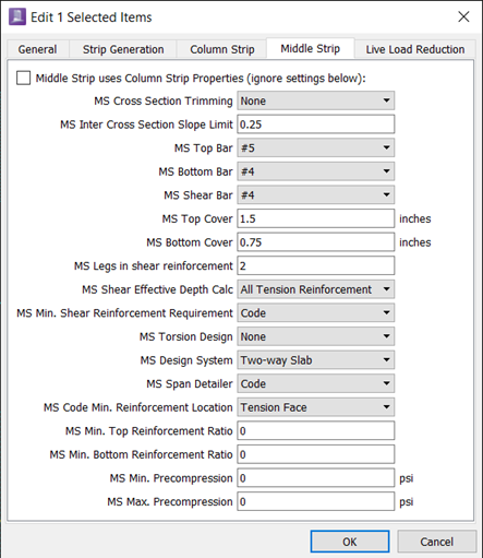
| Setting | Description |
|---|---|
| Middle Strip uses Column Strip Properties | Sets the middle strip properties to those of the column strip. |
Live Load Reduction tab

| Setting | Description |
|---|---|
| Max live Load Reduction | See Live Load Reduction Notes for information on RAM Concept ’s implementation of live load reduction. |
| User specified LLR parameters | See Live Load Reduction Notes for information on RAM Concept ’s implementation of live load reduction. |