Corridor Misc.
You can access this tool from the following:
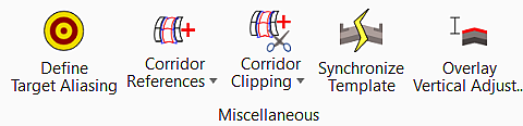
Ribbon: Corridor > Miscellaneous
|
Select in the Toolbox |
Description |
|
Defines target aliases for a corridor. You can use target aliases to create the desired results when working with multiple surfaces without having to edit the template from the template library. |
|
|
Used to add the selected graphical elements to the corridor, and reprocess. Graphical elements that are target via features in Corridor Modeling will not be utilized until they are added as a corridor reference. Examples include shoulders, curbs, sidewalks, etc. This enables the user to target specific shoulders on one roadway, while ignoring shoulders on adjacent roadways by referencing elements to a specific corridor. Elements can be referenced to more than one corridor. |
|
|
Used to remove the selected graphical elements (previously included via the Add Corridor Reference) from the corridor, and reprocess. |
|
|
The "clipping" feature allows you to remove areas of overlap when working with MicroStation elements or multiple corridors. In the following illustration, the rectangle (MicroStation element) is defined as the clipping reference for the corridor. Therefore, all elements of the corridor within the rectangle are "clipped" or deleted, leaving only the horizontal geometry element. When working with multiple corridors where a corridor intersects a crossing roadway (defined by a second corridor), clipping would be used to remove all overlapped features within the intersection. |
|
|
Removes a clipping reference and reprocessed the corridor model without the reference. It does not delete the actual clipping reference element. |
|
|
Updates a template within a template drop with the template of the same name from the current template library. Any changes previously made to the template in the template drop are overwritten with warning. |
|
|
At each processed station, this command determines the ideal PGL point based on the input criteria and the distance from the top of the template to the existing ground. |


