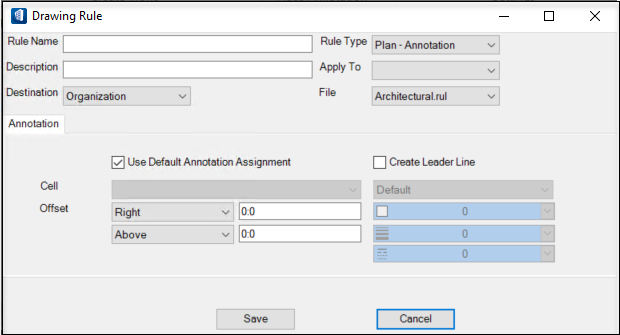
Drawing Rule dialog
Used to create, copy or edit drawing rules used in Building dynamic views. The Drawing Rule dialog provides settings to create Mechanical or Architectural drawing rules. Structural drawing rules are created using the Structural Drawing Resymbolization Rule dialog .
- Apply Drawing Rules
dialog - Select
 ,
,
 or
or

- (Mechanical) Drawing Rules Manager - Select New.
Design projects must be presented in the form of drawings and annotated 2D views to specify what is required for construction. OpenBuildings Designer maintains a robust drawing rule utility, which permits you to change the representation of model geometry and provide annotations. Rules use the DataGroup System, the part and family system, and selection criteria as a means to identify collections of objects, to focus rule impact. Drawing rules and drawing preferences are set to prepare for construction drawings.
Drawing rules focus on enhancing the drawing annotation process and save production time by automating annotations. Drawing rules leverage the existing Annotate Tool settings which support both graphics and DataGroup attributes. Annotations are associated to criteria, forming a rule that can be processed as part of a drawing view, permitting DataGroup objects to be automatically annotated.
Drawing rules save production time and enhance project quality and coordination. They reduce the need to perform repetitive tasks and they enable teams to focus on the project. Drawing rules address unique Building discipline drawing nomenclature and provide clarity.
You can have multiple rule files at Organization, Workspace and Workset level. A drawing rules setting file exists for each discipline at Organization level. For Workspace and Workset location specify the directory location and file name for the rule file using configuration variable. Check Configuration variables for more information.
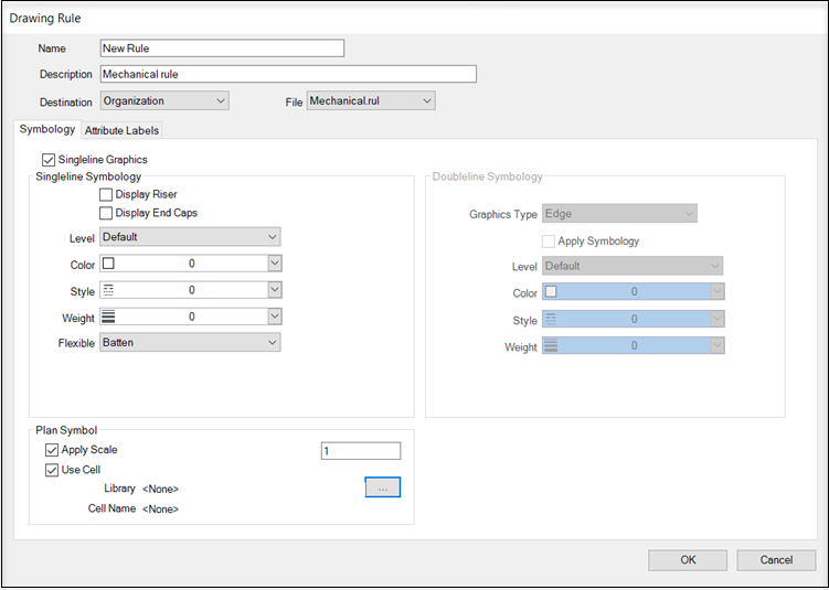
The main tabs in the Drawing Rule dialog set and characteristics. The Symbology tab defines double line symbology by setting a graphics type and a cell to plan symbol. The Attribute Labels tab provides controls for setting annotation text position, presentation and symbology characteristics for each attribute type.
| Setting | Description |
|---|---|
| Rule Name/Name | Sets the rule name displayed in the Apply Drawing Rules dialog, and in the View Attributes dialog Building panel Architectural or Mechanical tabs. This field must be filled to save the rule definition. |
| Description | Sets a brief description for the rule function. |
| Rule Type (Architectural rules) | Select the type of rule that best describes the rule function, from a list. This value enables you to manage and sort rules based on type. |
| Apply To (Architectural rules) | Select the Building element to which the rule applies, from a list of Building elements in the DataGroup catalog. |
| Destination |
Allows selecting the destination folder of the rule file path. Select Organization, Workspace, or Workset location.
|
| File | Sets the destination file name where the new rule is stored. |
| Annotation tab | Contains settings used to control the annotation symbol and symbol placement in Architectural drawing views, relative to the Building element. |
| Symbology tab | Contains controls used to resymbolize top and side view graphics in Mechanical drawing views. |
| Attribute Labels tab | Contains controls used to manipulate Mechanical labels. |
| Save/OK | Saves newly created, copied, and edited Architectural/Mechanical drawing rule definitions and closes the dialog. |
| Cancel | Discards any changes and closes the dialog. |