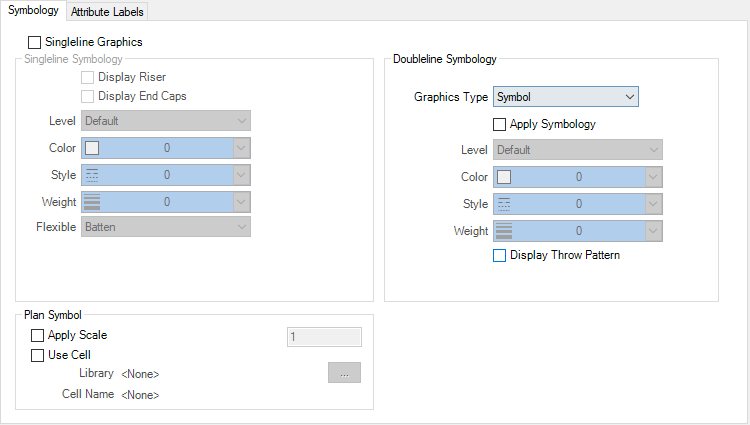
| Singleline Grpahics
|
When on, the
Singleline Symbology settings group is
activated. Single line drawings are generated by resymbolizing center line
elements stored in Mechanical components as 2D plan symbols. Drawing
composition output contains information about all 2D plan
symbols oriented parallel to the section plane. This allows for dynamic single
line representations..
When off, the
Doubleline Symbology settings group is
activated. Double line drawings are generated by resymbolizing graphical
elements stored in Mechanical components as a 2D Plan Symbol corresponding to
the six standard view orientations (top, bottom, front, back, left and right).
Drawing composition output contains information about all 2D
plan symbols oriented parallel to the section plane. This allows dynamic double
line representations.
|
| Display Riser
|
When on, risers cut by the drawing plane are
resymbolized using the single line symbology settings, and appear in the
drawing.
|
| Display End Caps
|
When on, lines that are perpendicular to the
centerline mark the ends of each component. The width of the end cap lines is
the same as the dimension of the component as seen from the cut plane.
|
| Level
|
Sets the level for visible lines.
|
| Color
|
Sets the color for single lines.
|
| Style
|
Sets the line style for single lines.
|
| Weight
|
Sets the line weight for single lines.
|
| Flexible
|
Sets appearance of resymbolized flex duct to
familiar styles.
-
Batten – Represents flex duct with a
batten line style between connections
-
Singleline – Represents flex duct as
extracted, but resymbolized according to symbology settings
-
Accordion – Represents flex duct using a
zig zag pattern. Use the
Width and
Height settings activated by this
selection to set accordion dimensions.
-
Arc – Represents flex duct with an arc
between connections. Use the
Direction and
Height settings activated by this
selection to set arc characteristics.
Note: Height
sets distance of the arc highest point relative to a straight line between
connections.
|
| Graphics Type
|
A double line rule can contain multiple sets of
symbology definitions, each resymbolizing a different graphics type. Turn on
Apply Symbology to activate symbology
settings for each graphics type. When off, symbology reverts to the basic part
definition settings.
-
Edge – Activates symbology settings for
visible sides and edges.
-
Centerline – Activates symbology
settings for center lines.
-
Insulation – Activates symbology
settings for insulation.
-
Lining – Activates symbology settings
for lining.
-
Symbol – Activates symbology settings
for air flow symbol. Graphic type Symbols enables additional
"Display Throw Pattern" settings.
|
| Apply Symbology
|
When on, symbology settings for all graphics types
become available for manipulation.
-
Level – Sets the level for double lines.
-
Color – Sets the color for double lines.
-
Style – Sets the line style for double
lines.
-
Weight – Sets the line weight for double
lines.
|
| Display Throw Pattern
|
When set, enables throw pattern in DV for
rectangular (outlet) ceiling diffusers.
Important: This setting is mandatory to
view the throw pattern symbol in DV.
|
| Apply Scale
|
Sets the scale factor to the cell being used as the
plan symbol. When on, applies the set scale to the plan symbol.
|
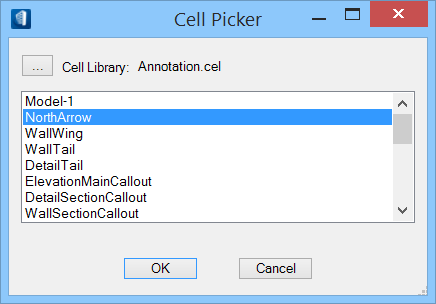
| Use Cell
|
When on, the browse button in the
Plan Symbol settings group is activated.
Click it to open the Cell Picker dialog. Here, you can select cells to use as
plan symbols or browse for and select cells from the Cell Library dialog.
|
| Library
|
Displays the name of the selected cell library.
|
| Cell Name
|
Displays the name of the selected cell.
|