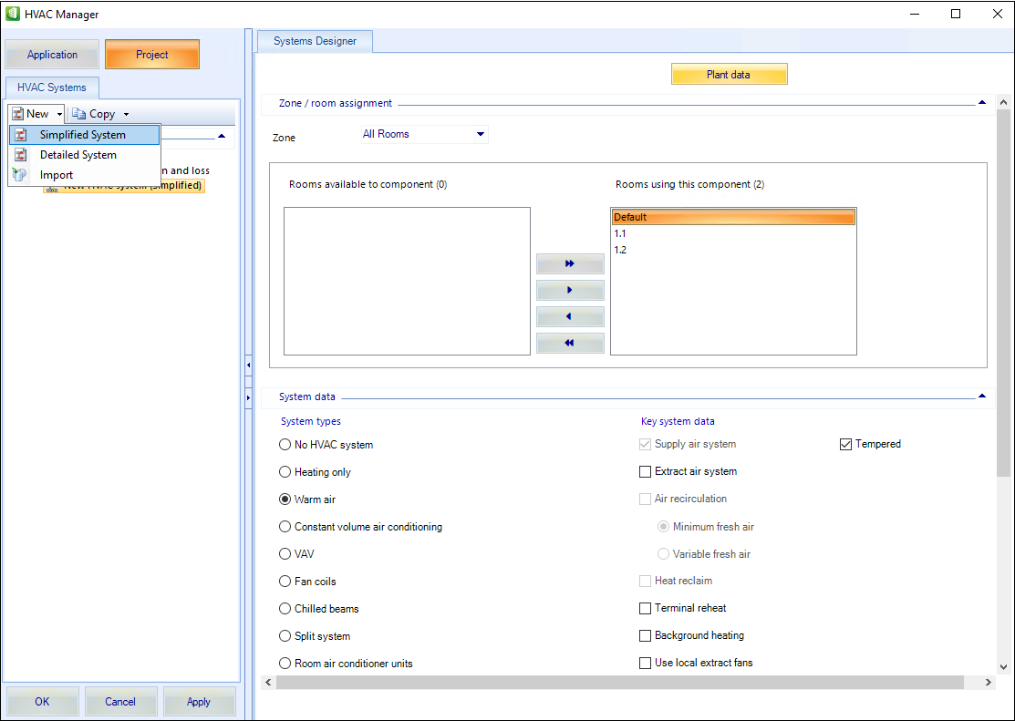
Systems Designer Tab
The System Designer Tab contains a set of HVAC systems and the data associated with it. If any of these systems are used, check the data associated with the system. For example, a heating system needs the defined emitter type, and an air conditioning system may be supply only. Also, check the central plant items such as boilers and chillers that supply the HVAC system equipment and this data can be defined using the Plant data program.
| Setting | Description |
|---|---|
| Plant data |
The Plant data form gives you access to data for central plant equipment such as boilers that are used by HVAC systems. |
Zone/room assignment
| Setting | Description |
|---|---|
| Zone | The defined zones can be selected from the list. |
| Rooms available to component | Displays all the available rooms. |
| Rooms using this component | Displays the rooms that use the component. |
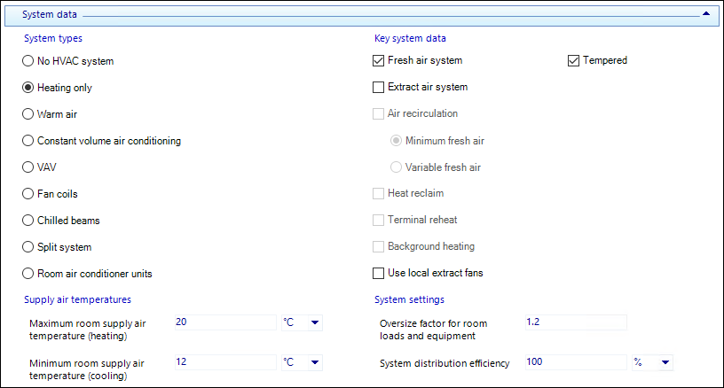
System data
When a particular HVAC system and the zones that use the system are selected, the data associated with the particular HVAC system can be moved on and defined.
Supply/extract air
If the selected system has supply air, then the criteria for supply fresh air is specified on this tab. Supply fresh air can be specified as an air change rate, per person or per square metre.
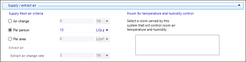
If extract air only is used (no supply air), then the extract air change rate needs to be specified.
If a supply air system is used that supplies several rooms, then one room must be selected as the control room, this room will be used to control room temperature and humidity.
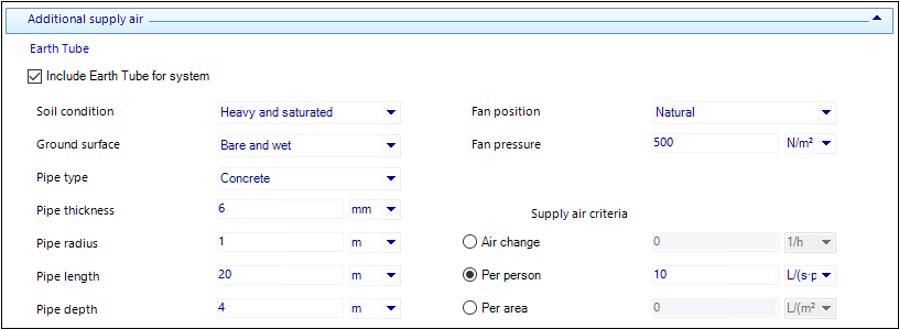
Additional supply air
Additional supply air can be provided to all rooms associated with the system by selecting "Include Earth tube for system" on the Additional supply air tab. Once included as part of the system, the user can specify various parameters associated with Earth Tube geometry, soil conditions, fan performance, and supply air flow criteria.
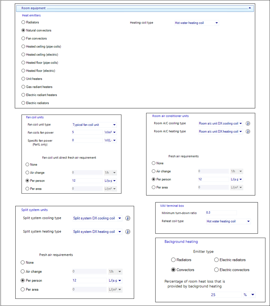
Room equipment
If the HVAC system uses room equipment (e.g. heat emitters, VAV terminal boxes, fan coil units etc) then the data relating to a typical room unit is specified on the Room equipment tab.
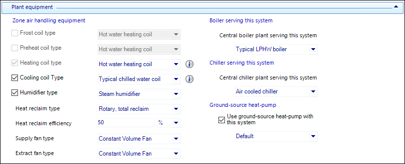
Plant equipment
All the HVAC air handling equipment such as coils, humidifiers, fans and heat reclaim is specified on the Plant equipment tab. The required piece of equipment can be selected from a list of generic equipment. For heating coils you can select a hot water coil (served by the specified boiler) or a direct fired electric or gas coil. For cooling coils, you can select a chilled water coil (served by the specified chiller) or a DX coil. You can also define the boiler and chiller serving the HVAC system, this uses the current list of available boilers and chillers, this data can be specified using the Plant data program.
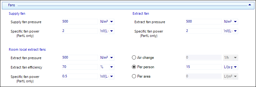
Fans
If supply, extract or local extract fans are specified then the supply and extract fan pressures on the Fans tab should be defined. Local extract fans can be specified for most systems. It is assumed that each room has a local extract fan. The local extract fan pressure efficiency and air flow criteria are specified on the Fans tab.
Vent
Ventilation controls can be set up to control a ventilation system which provides night-time ventilation to avoid overheating.
If night-time ventilation control is specified, then the user must specify applicability schedules for annual energy consumption simulations. Applicability schedules define when the control is "applicable" or "available". A schedule value of 1 means the control is applicable (available to operate if the proper conditions exist), while a schedule value of 0 means the control is not applicable/available for that hour of the simulation.
In addition to applicability schedules, design day and annual temperature schedules must also be specified. At least one room being served by this HVAC system must be above the specified temperature schedule value for the "night cycle" ventilation fan to operate. If all rooms served by this HVAC are below the temperature schedule value, then the night ventilation fan will not operate.
The lower limit temperature defines the minimum indoor air temperature for night-ventilation operation. If the dry-bulb temperature in any room served by this system drops below this minimum temperature, then the night ventilation fan will not operate. The Required temperature difference defines the minimum temperature difference between outdoor air and the controlling room indoor air temperature. The controlling room temperature minus the outdoor air temperature must be greater than this temperature difference for night ventilation to occur.
The night venting flow fraction defines the fraction of the air handler fan's design flow rate that will be applied when night ventilation is active. The night venting fan pressure defines the air pressure rise that the night ventilation fan will operate against when it is active.
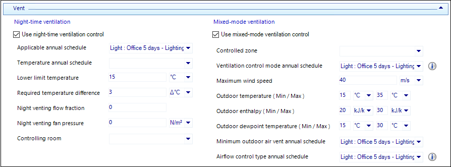
If mixed-mode ventilation is specified, the system is controlled to prevent simultaneous natural ventilation and HVAC air handler operation with the goal of maximizing natural ventilation in order to reduce heating/cooling loads that must be met by the HVAC system. The air conditions in the Controlled zone (room) are used to determine if natural ventilation should be provided.
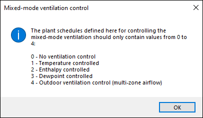
The user must then specify the maximum wind speed as well as minimum and maximum values for outdoor temperature, enthalpy and dewpoint temperature. If the wind speed exceeds the maximum defined value, then mixed-mode ventilation is shut off. Depending on the mode specified in the ventilation control mode schedule (e.g., dry-bulb temperature, enthalpy or dewpoint temperature), the minimum and maximum outdoor temperature/enthalpy values define the limits beyond which mixed-mode ventilation will be deactivated. For example, if temperature controlled is specified, then mixed mode ventilation will be shut off if the outdoor dry-bulb temperature is above the maximum outdoor temperature value or below the minimum outdoor temperature value.
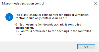
Minimum outdoor air ventilation schedules are also defined for the annual energy consumption simulations. These schedule only apply for periods when "Outdoor ventilation control" is specified (ventilation control mode schedule value = 4). Schedule values are outdoor ventilation, defined in air changes per hour (ACH). The outdoor air entering the controlled zone (room) from natural ventilation (window and/or door openings) is initially calculated and compared to the minimum outdoor ventilation air schedule value. If outdoor air from natural ventilation is less than the minimum OA ventilation schedule value, then natural ventilation is shut off (i.e., window and/or door openings are closed) and the HVAC system may operate if needed. Otherwise, the natural ventilation is on and the HVAC is shut off. Since the OA ventilation entering the controlled zone (room) is determined as air from outdoors, this option only applies to a control zone (room) having at least one window or door exposed to outdoors.
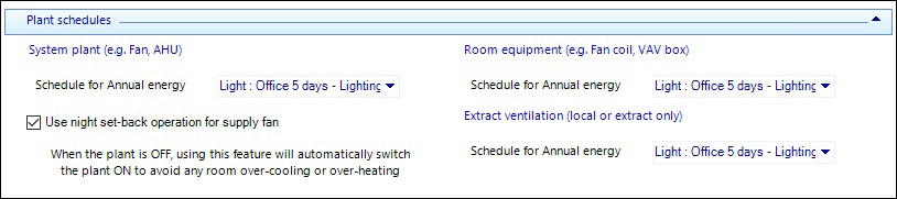
Plant schedules
Define schedules for plant operation for annual energy consumption simulations. An annual schedule must be defined for Annual energy calculations. When annual energy is simulated, the Annual energy schedules will be used.
The night set-back operation for the supply fan in the HVAC system can be specified optionally. If this is done, during annual energy simulation runs, the control system will automatically monitor the temperature in all rooms served by the system to check if they fall below the required scheduled room heating temperature or rise above the scheduled room cooling temperature. If this happens, the system fan will be switched on and the system will attempt to reach an acceptable temperature.
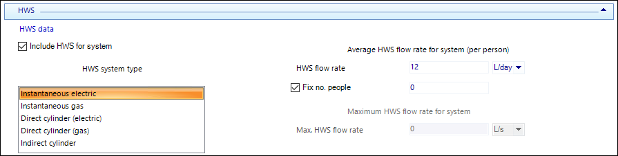
HWS
An HVAC system can have an HWS system associated with it. HWS systems are defined in the Plant data program. If the HWS system has been set up using an average HWS flow rate (litres/person/day), this value can be specified for the zone. If the HWS system has been set up using a profiled HWS consumption, the maximum HWS flow rate is specified for the zone. The annual profile for the HWS consumption is specified with the HWS equipment data in the Plant data program.