Plant data
The Plant data form gives access to data for central plant equipment such as boilers that are used by HVAC systems. A boiler can be set up on this form which could supply several HVAC system coils or emitters. Several different boilers could be defined, each of which may serve different HVAC systems. Parallel plant for boilers, chillers and cooling towers can be set up, so that the parallel assembly serves HVAC systems.
Boilers
Any number of different boilers can be defined. Some typical boilers are provided initially, these can be changed as required and further boilers added. Each boiler has a description. Boilers can be of the LTHW, MTHW, HTHW or Air-to-water heat pump types, or district heating can be specified. The boiler flow and return water temperatures are specified, these are used to compute system water flow rates. The simple boiler efficiency is specified, a part load efficiency curve is used for boiler performance. If the boiler maximum capacity is known, this maximum capacity can be specified and the boiler output will then be limited, even if this results in under-heating rooms and zones.
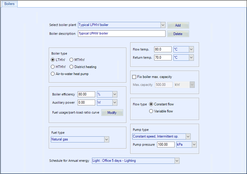
The boiler fuel type is specified, together with any auxiliary power required to operate the boiler. Auxiliary power is assumed to be electrical. A pump will be used to distribute hot water from the boiler to all the equipment connected to it. Various pump types are available. The pump pressure should be specified, this will be used to size the pump motor and compute pump energy.
A boiler operating profile must be defined for Annual energy calculations.
Make sure that the plant schedules for HVAC equipment (including night set-back) are compatible with the selected boiler schedule.
Chillers
Any number of chillers can be defined. Some typical chillers are provided initially, these can be changed as required and further chillers added. Each chiller has a description. Chillers can be of the air cooled and water cooled types or district cooling can be specified. Water cooled chillers need a cooling tower and the cooling tower serving the chiller must be specified. Check the data for the specified cooling tower to see that it is acceptable.
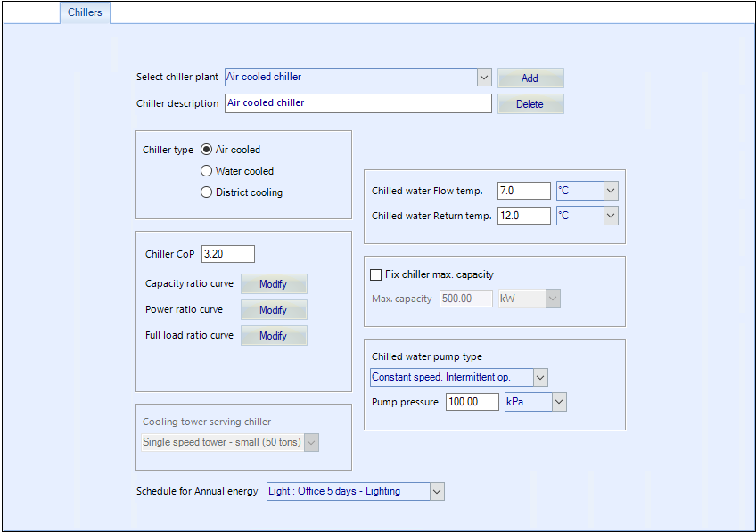
Chillers provide chilled water that is pumped to coils in HVAC systems that use the chiller. The chilled water flow and return temperatures are specified, these are used to compute chilled water flow rates. The simple chiller coefficient of performance (CoP) is specified, along with 3 performance curves (capacity ratio as a function of temperature difference, power ratio as a function of capacity ratio, and fraction of full load power as a function of part-load ratio). If the chiller maximum capacity is known, this maximum capacity can be specified and the chiller output will then be limited, even if this results in under-cooling rooms and zones.
A pump will be used to distribute chilled water from the chiller to all the equipment connected to it. Various pump types are available. The pump pressure should be specified, this will be used to size the pump motor and compute pump energy.
A chiller operating profile must be defined for Annual energy calculations. The annual energy schedules can be defined using the Annual schedules tab in the Profiles program. For design day simulations, the chiller is assumed to be always available for operation.
Make sure that the plant schedules for HVAC equipment are compatible with the selected chiller schedule.
Cooling towers
Any number of cooling towers can be defined. Some typical cooling towers are provided initially, these can be changed as required and further cooling towers added. Cooling towers are used to reject heat from a water-cooled chiller, so you only need to set up cooling towers to serve any chillers that you are using. Each cooling tower has a description. Cooling towers can be single speed or two speed. The modelling of cooling towers differs for single and two speed. For single speed, if the capacity is not known, typical data is assumed. If the cooling tower nominal capacity is known, this can be specified and the cooling tower output will then be limited, even if this results in inadequate cooling for the chiller.
Cooling towers provide cooling water that is pumped to the chiller that uses the cooling tower. A pump will be used to distribute cooling water from the cooling tower to the chiller connected to it. Various pump types are available. The pump pressure should be specified, this will be used to size the pump motor and compute pump energy.
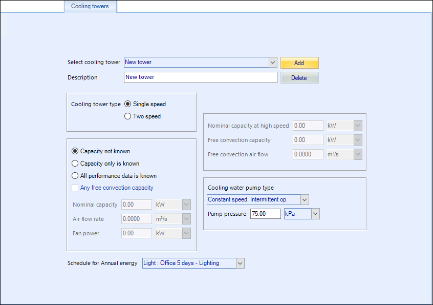
A cooling tower operating profile must be defined for Annual energy calculations.
Make sure that the plant schedules for the chiller and HVAC equipment are compatible with the selected cooling tower schedule.
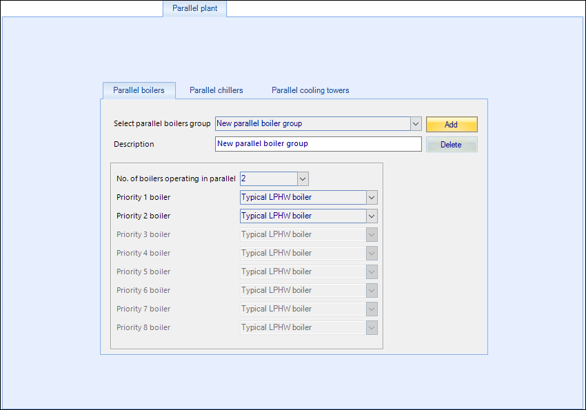
Parallel plant
Boilers, chillers and cooling towers can be operated in parallel if required. To set up a group of boilers operating in parallel, press the Add parallel boiler assembly button. Then enter a description of the parallel group. Specify the number of boilers in the group, then select each boiler that you wish to include in the group, in the order of operating priority.
A group of parallel chillers or cooling towers can be set up in exactly the same way, using the relevant parallel equipment tabs.
Once you have set up a parallel plant group, the group can be used in the same way that an individual piece of plant is used. For example, you could set up two boilers operating in parallel and call this Parra Boilers. When you come to specify the boiler plant for an HVAC system, you can select an individual boiler or you can select the boiler group Parra Boilers.
When plant is being simulated and a parallel plant group is used, plant items are operating in sequence, as the demand changes, with the first specified plant item in the group being switched on first. As the demand increases on the parallel group, the next item in the list will be switched on to cater for the demand. In this way, at times of low demand, a single plant item only may be switched on since this may be sufficient for the low demand.
If you define parallel plant groups, you should only use the parallel group, you should not try to use the individual plant items. For example, if Boiler 1 and Boiler 2 are used to set up the parallel boilers group Parra Boilers, then you should never try to use Boiler 1 or Boiler 2, because these boilers should only operate in the parallel group Parra Boilers.
Fuels
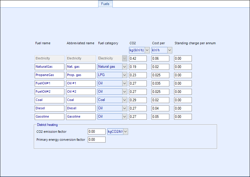
These categories of fuel enable almost any type of fuel to be set up as data for energy cost and CO2 production means that the fuel data is independent of calorific value.
HWS
Any number of HWS units can be defined. Some typical HWS units are provided initially, these can be changed as required and further HWS units added. HWS units are referenced by HVAC systems, this enables the number of people served by the HVAC system to be taken into account when the HWS water requirement is computed.
For all types of HWS units, a description is entered. The required HWS flow temperature and the incoming cold water mains temperature is specified.
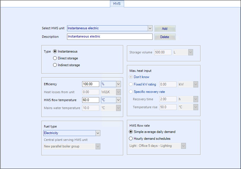
- Instantaneous - water is heated by a local direct fired heater, as it is required for use, no storage of hot water is provided. The fuel type for the HWS heater is specified, together with the unit efficiency.
- Direct storage - water is heated by a local direct fired heater and some hot water storage is provided in the unit. The storage volume, heater fuel type, heater efficiency and heat losses from the unit are specified. If the heater rating is known, it can be specified, otherwise it will be computed during simulation runs.
- Indirect storage - water is heated indirectly by a boiler that serves the HWS unit. Hot water is stored in the unit. The storage volume and heat losses from the unit are specified. If the heater input is known, it can be specified, otherwise it will be computed during simulation runs. The boiler that provides heat to the HWS unit must be specified.
The amount of hot water produced by the HWS unit can be specified as a simple average daily demand or using hourly demand schedules. If Simple average daily demand is used, the required hot water flow rate (litres/person/day) is specified for each HVAC system that uses the HWS unit. If Hourly demand schedules are used, you must specify an annual energy schedule of HWS flow rates, and these schedule profiles are applied to the Maximum HWS flow rate for System as defined in the HVAC systems program, HWS tab.
CHP
Combined heat and power systems can be set up to generate electricity and to heat hot water by recovering energy that would otherwise be wasted .
Traditionally, electricity is generated at a central power plant, and on-site heating and cooling equipment is used to meet non-electric energy requirements. In a CHP system, the electricity is produced onsite, and the thermal energy is recovered to be used for heating the building or other hot water needs.
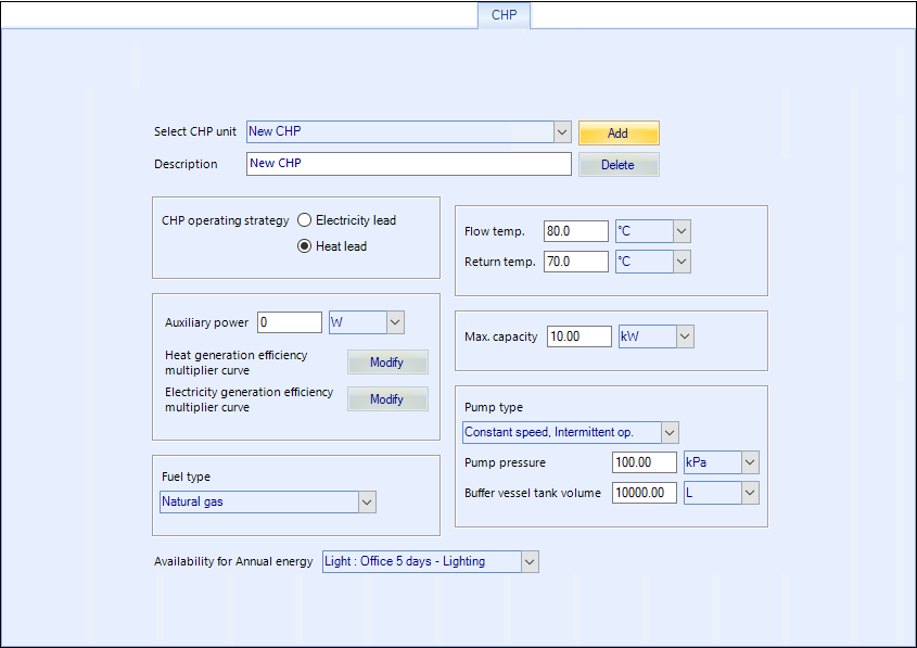
The inputs required to define a CHP are the electrical output capacity, flow and return temperatures, auxiliary power, fuel source type, pump type and pump pressure, buffer vessel tank volume and scheduling information.
Other CHP performance parameters can be viewed and modified by selecting the available efficiency curves for heat generation and electrical efficiency as a function of percent loading.
Heat pumps
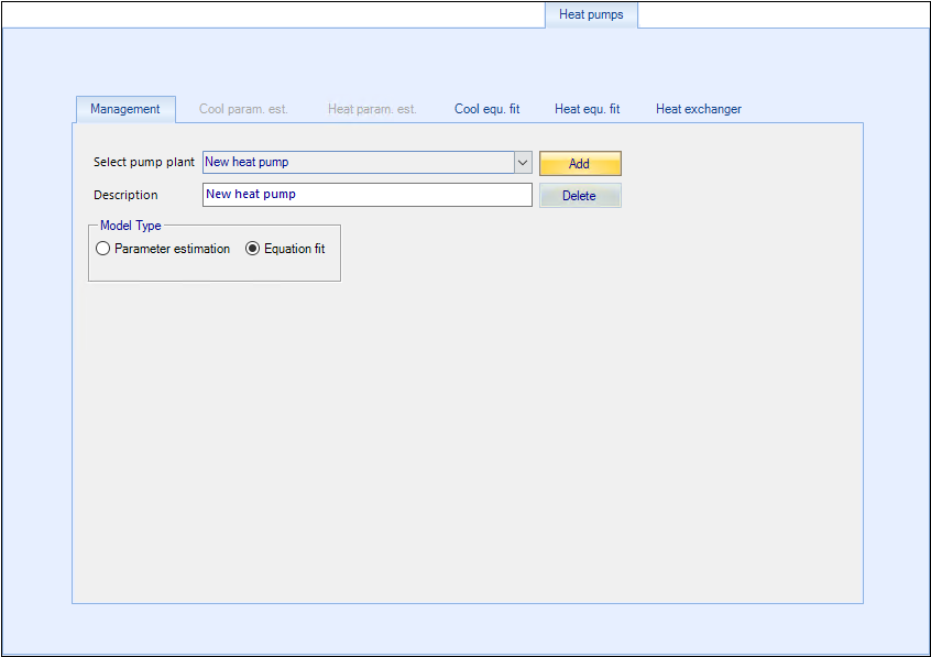
Any number of water-to-water heat pumps can be setup. Two modelling types are provided when setting up these heat pumps.
| Setting | Description |
|---|---|
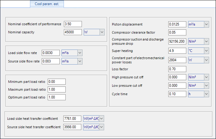
| Cool param. est. | The tab is enabled when the Parameter estimation model type is selected. The Parameter estimation model is used in lieu of manufacturer’s data. Values entered for nominal cooling and heating performance coefficients, heat transfer coefficients, nominal cooling and heating capacities, flow rates, part loads, and compressor characteristics are used by Simulator to model heat pumps. |
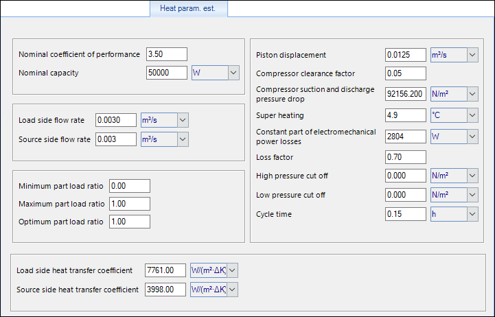
| Heat param. est. | The tab is enabled when the Parameter estimation model type is selected. The Parameter estimation model is used in lieu of manufacturer’s data. Values entered for nominal cooling and heating performance coefficients, heat transfer coefficients, nominal cooling and heating capacities, flow rates, part loads, and compressor characteristics are used by Simulator to model heat pumps. |
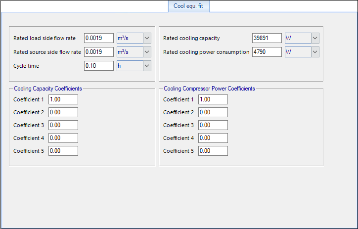
| Cool equ. fit | The tab is enabled when the Equation fit model type is selected. The Equation fit model is used when manufacturer’s data is available. Values entered for rated flow rates, rated cooling and heating capacities, and cooling and heating capacity and compressor power coefficients are used by Simulator to model heat pumps. |
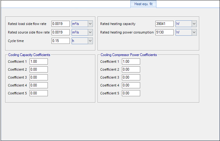
| Heat equ. fit | The tab is enabled when the Equation fit model type is selected. The Equation fit model is used when manufacturer’s data is available. Values entered for rated flow rates, rated cooling and heating capacities, and cooling and heating capacity and compressor power coefficients are used by Simulator to model heat pumps. |
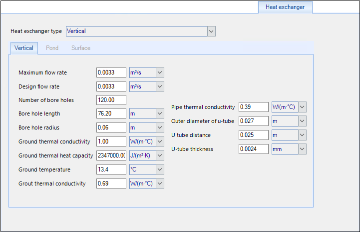
| Heat exchanger | Heat exchanger is used to transfer heat into the building from the ground or a water source located adjacent to the building. This input screen is used to select heat exchanger types (vertical ground HX, ground surface HX or surface water pond), and enter detailed information about their design into the Simulator. |