Used to place active annotation symbol cells on DataGroup enabled
elements in drawing and sheet models. Also used to place labels for multiple
Mechanical Elements, in a stacked manner, dynamically controlled by mouse
movements.
Used to place active annotation symbol cells on DataGroup enabled
elements in drawing and sheet models. Also used to place labels for multiple
Mechanical Elements, in a stacked manner, dynamically controlled by mouse
movements.
Accessed from:
- Ribbon:
Building Design >
The single placement method requires you to click on an
element with valid DataGroup properties, prompting the appropriate cell to
display as specified in the
Annotation Parameters
dialog. The cell appears dynamically on the pointer and is placed with a second
data point. The cell origin is placed at the location where the placement data
point is entered and the angle of placement is controlled by the active angle.
Note: The tool works
across attached reference files. For example, when a 3D model is attached as a
reference to an open design file, you can place datagroup annotations when
selecting valid elements in the reference file. When updates are made to
datagroup instance data in the 3D model, datagroup annotation cells in the open
DGN file are also updated. Updates to datagroup annotation cells also occur
when the DGN file containing them is opened. Dependency linkages across
reference files, between datagroup annotation cells, continue as long as
reference files remain attached. Reference files that are detached and then
reattached loose dependency linkages between datagroup annotation cells.
The stacked annotation method requires you to click on
valid duct or pipe Mechanical discipline components (also with valid DataGroup
properties) to display the appropriate cell. The cell appears dynamically on
the pointer with a leader attached to the initial click location. As you move
the pointer, annotations are added in a stacked manner for all Ducts and Pipes the leader line intersects. The final stacked annotation is
placed with a second data point.
Remember: Stacked annotations are enabled
for plan view oriented 2D drawing and sheet models.
| Setting | Description |
|---|
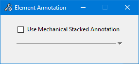
| Use Mechanical Stacked Annotation
|
When checked, enables symbol attribute settings
below. When unchecked, the active annotation symbol gets placed as a effect
place DataGroup Annotation tool workflow.
Note: Always check
the
Use Mechanical Stacked Annotation setting
to proceed with stacked annotations. Also, the model should have the drawing
rule based attributes or custom label attributes defined in the drawing rule (see, the Add Attributes in
Attribute Label tab of Drawing Rule).
|
| Show/Hide More info
|
Enables only when the
Use Mechanical Stacked Annotation is set.
When clicked, the triangular icon collapses and expands, thereby displaying the
attribute settings that can be applied for stacked annotation.
|
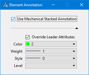
| Override Leader Attribute
|
When checked, enables leader attribute settings
below applicable for stacked annotation. The current settings override the
default leader attributes, and modified symbology applies to leader
being placed. When unchecked, the default symbology is effective.
|
| Color, Weight, ..
|
Used to set the label attribute that make up
annotation graphics.
- Color - Sets
the color of the leader line symbology.
- Weight - Sets
the weight of the leader line symbology.
- Style - Sets
the line style of the leader line symbology. Styles are limited to the
predefined line styles 0 to 7 and the ByLevel style.
- Level - Sets
the level on which the leader line will appear
|
Stacked Annotations
reviewed
Stacked annotations work in plan views for placing
Mechanical rule based annotations in stacked manner to ducts and pipes in the drawing. Element
Annotation generates the annotation as you
"mark" elements for labelling. Stacked annotations
require selecting a valid duct or pipe components
The tool allows you to use the mouse to choose different
elements, and stacks the individual annotations in a different slots. If you
choose two pipes, then it puts two horizontal lines. Moving mouse further may
overlap more elements, thus growing the stack. The labels appear in the order
the elements are overlapped in the drawing.