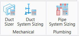
Pipe System Sizing
 Used to compute and based
on hydraulic pressure, velocity requirements perform piping sizing algorithms,
and rebuild pipe system after resizing by optimizing route path pipe sections.
Used to compute and based
on hydraulic pressure, velocity requirements perform piping sizing algorithms,
and rebuild pipe system after resizing by optimizing route path pipe sections.
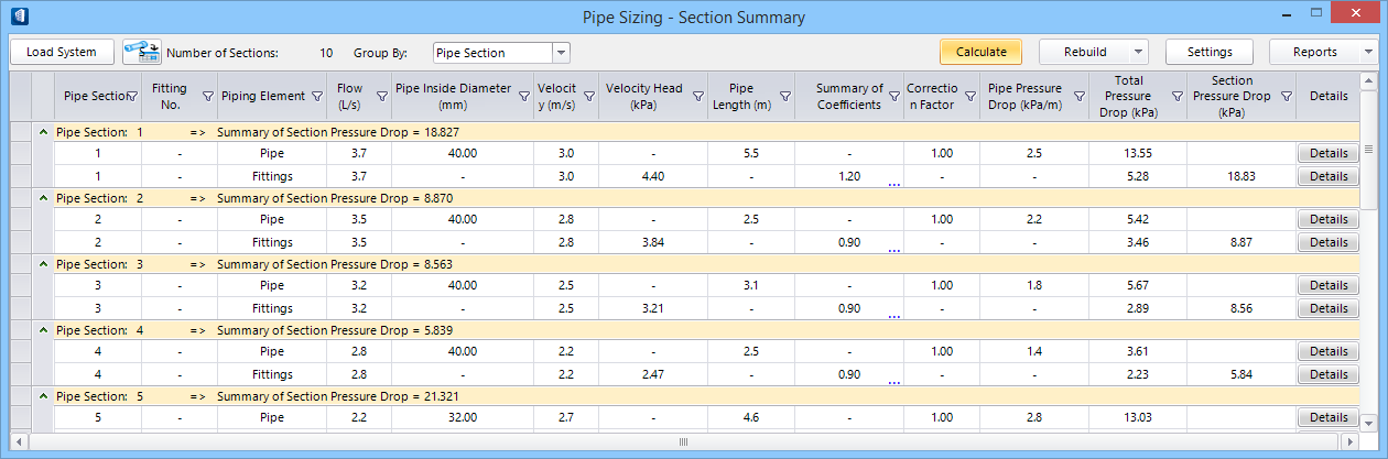
The dialog is used to load, set and compute pipe sizing parameters to construct an optimized pipe system by Equal Friction method. The dialog also allows to rebuild the resides pipe system and write to model, and generate various reports.
| Setting | Description |
|---|---|
| Load System | Loads the active piuping system. When selected, and
a valid route is loaded by selecting a source or first component in the route
in the view, opens the
Assign & Analyze Connection dialog, where flow types are
mapped to the available connection ends. The Load System button turns
 , and remains
animated until one of the mapped ends is selected to process. The route is then
fully loaded with pipe section data populated in the summary table. , and remains
animated until one of the mapped ends is selected to process. The route is then
fully loaded with pipe section data populated in the summary table.
|

|
When clicked the pointer highlights the pipe section row corresponding to the currently selected segment in the route geometry. Based on the Sectioning settings in Pipe Sizing - Settings, the pipes expanded in a given section are highlighted. |
| Number of Sections | Displays the number of sections comprised in the active pipe system. |
| Group By | The filtering and grouping list options are provided
for listing the pipe components.
|
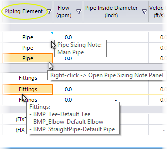
| Pipe Sizing Table list | The pipe sizing table lists various columns that
summarise pipe section numbering, fitting identifications, size and dimensions
and physical properties associated with each fitting.
Note: Refer to the
section
Working with Pipe System Sizing dialog for behaviour,
functioning and use of various dialog fields.
The following are the columns, arranged from left
to right.
|
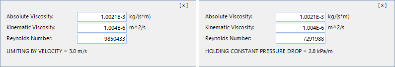
| Calculate | Calculates the pipe sizing by internally computing
the flow rate, velocity parameters against the physical dimension of pipe and
pipe fittings lay in the system. Values altered in CLC Summary table and
overrides, if any are reflected in the calculation.
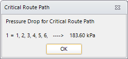
The critical route path report pops up indicating the path
numbers of critical path and the value of pressure drop. The number in the left
side indicates the path numbers and the numbers in the right side indicate
section numbers and the resultant pressure drop. The pressure drop value is
significant for paths having considerable resistance to flow. Clicking OK
dismisses the pop up dialog and the critical path is highlighted in the
geometry. The corresponding section rows in the table also highlighted in
different color shade. Activated Calculate button turns
 , and remains
animated until you click
OK on the Critical Route Path pop up. When
any velocity constraints is encountered, the message prompt alters
Pipe Velocity Limiting occurring. , and remains
animated until you click
OK on the Critical Route Path pop up. When
any velocity constraints is encountered, the message prompt alters
Pipe Velocity Limiting occurring.
|
| Rebuild | Enabled after Calculation. Rebuilds the active
system for altered parameters set in the pipe system, including dimensions of
pipe fittings in the pipe sections. This is done to achieve a desired Flow Loss
Coefficient value. The geometry and properties associated with the pipe system
are subjected to change in the rebuild.
 , and remains
animated until the rebuild (Write to Model) command is executing. Mismatch in
the resized fittings, if any, may cause disconnects and you will be alerted
with the
View Disconnects dialog. You can locate and delete
disconnected center lines and revise the route for reloading the system. , and remains
animated until the rebuild (Write to Model) command is executing. Mismatch in
the resized fittings, if any, may cause disconnects and you will be alerted
with the
View Disconnects dialog. You can locate and delete
disconnected center lines and revise the route for reloading the system.
|
| Settings | Opens Pipe Sizing - Settings dialog where design data, size criteria, and reporting options are set. |
| Reports | Provides options to generate pipe sizing reports of
various needs:
|