Resize System - walk through Pipe Sizing
Arrange the view windows to make the geometry of currently loaded route visible in the working view. This is required during the walk through to access and analyze associated fittings in the pipe sections. When a fitting or section of critical path is highlighted in Pipe Sizing table, it also gets selected in the geometry. The objective of walk-through is to reduce the pressure loss in critical paths in the route. Then run Calculate. Work with design data followed by fixing pipe details, including diameter, material, and types of piping fittings, followed by loss coefficients and any overrides, as required to achieve smaller value for pressure loss.
The below steps illustrates the main stages when you walk through in a typical pipe sizing workflow: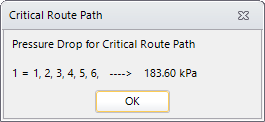
- (Optional)
Run the
option.
The Pipe Sizing Reports All Routes report window opens listing all paths in the route and their pressure loss values in ascending order.
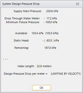
- Populate Pipe Sizing summary by loading a valid system and run Calculate. The system interactively prompts intermediate values and suggested settings to tune in Settings and Summary dialogs.
-
Analyse the Pipe Sections in critical path. Study the pipe section
data in the summary table. Pipe fittings and valves disturb the normal flow of
liquid, the resistance to flow causes head drop due to friction. When the flow
rate increases, the velocity of the liquid increases at the same rate. The
friction or resistance to flow (due to viscosity) also increases. When the
inside diameter is made larger, the flow area increases and the velocity of the
liquid at a given flow rate is reduced.
The head drop in a pipe is predicted as below:
- Get the flow rate you put through that pipe.
- Divide the length of pipe by 100 and multiply by the "Head drop per 100'" value.
The altered values are to intent reducing pressure drop in the section and equalize the pressure across all section.
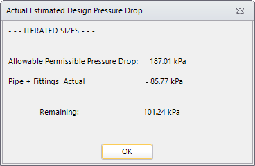
The "Iterated Sizes" prompt follows when loaded system being calculated. This helps to redefine the system components within allowable margins of pressure drop. - When changing and locking the diameter of pipes, consider the effect; if you use smaller pipe, it would restrict the flow of water. The reduced flow would reduce the pressure loss in the pipes, resulting in more pressure. You can adjust the supply main pressure and/or limiting velocity of main pipe in Settings dialog to compensate the altered pipe sizes.
-
Recalculate and observe critical path status. When pipes are set
for desired values you can walk through Fittings.
Fittings category may have more than one piping component, and analysed further in the Component Loss Coefficient (CLC) Summary table.
-
Double click in the
Summary of Coefficient column.
The Component Loss Coefficient Summary dialog opens listing all sections and type of fittings in it.
-
Observe the loss coefficient and reset the values and/or add
override, as required. Apply/reassign correct ASHRAE fittings by selecting a
valid one from the tree view list.
This is done to components that will have improved performance and grade in design, e.g. added insulation lining to a pipe section, using different material pipes to limit velocity etc.
- For fittings assigned Manufacturer Fitting nos., will have standard loss coefficient values as published in the standard (e.g. ASHRAE) table. You will see a standard Loss Coefficient value assigned to each fitting. Looking at the values derived internally by the parameters (say, for a given r/D, for an elbow, or Qs/Qc for takeoff fittings) in case of Node-Branch, you may alter their Loss Coefficient overrides and set correction factor value to derive a minimal loss. You may need to revise the Settings, for example to alter Limit Pipe velocity, or set right the Supply main pressure, etc.
-
The default correction factor value for pipes and fixtures are set
to 1.0, however can be altered to expect desired pressure drop in the section.
Setting override suppresses the correction factor or drop value for the fitting.
Values set in CLC Summary table will also reflect in Pipe Sizing table.
-
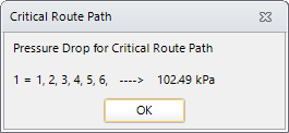
Switch to Pipe Sizing summary and repeat the
Calculate.
Repeat the steps of calibrating drop and coefficient values for next critical path until all sections are balanced for constant pressure drop.