Working with System Sizing dialogs
Introduction to Sizing dialog controls and mouse hover.
The Duct / Pipe System Sizing section summary is the main interface for system sizing. Using this dialog you set design data, manipulate ducts and fittings properties and feed permissible values of fluid and air flow parameters and using the equal friction method compute optimized flow characteristics.
The following illustrations depict the functioning and use of various dialog fields.
- Collapse/Expand
— The top headed arrow (
 ) indicates collapse. Clicking it
collapses the target section list.
) indicates collapse. Clicking it
collapses the target section list.
Similarly, clicking the Expand (
 ) expands the section list, there
by toggling the icon.
) expands the section list, there
by toggling the icon.
- Row
Indicators — Selecting a row by clicking (in non editable field)
will display the arrow
 icon in the leftmost column; and
turns to a pencil
icon in the leftmost column; and
turns to a pencil
 icon when an editable field in
the selected row is clicked. The arrow
indicates currently selected duct
section. The current duct section highlights the corresponding segment geometry
in the route in the view. (On the other hand, selecting a segment in the route
geometry and clicking
icon when an editable field in
the selected row is clicked. The arrow
indicates currently selected duct
section. The current duct section highlights the corresponding segment geometry
in the route in the view. (On the other hand, selecting a segment in the route
geometry and clicking
 brings the arrow focused on the
corresponding row.)
brings the arrow focused on the
corresponding row.)
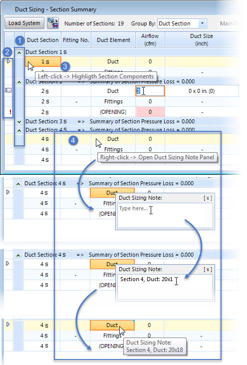
- Cell tool tip — Hovering mouse over the fields such as a value in Duct Section prompts a tool tip "Left-click -> Highlight Section Components". Clicking in such cell highlights the component by turning the cell appearance in different color and border.
- Duct/Pipe
Notes — The cells in Duct or in Pipe column can have a comment
attached to the ducts or pipes. The
opens a Note panel where you can write comment about the
duct or about the pipe, in case of pipe sizing workflow in respective segment.
The commented cell is indicated with a blue triangular mark in the top right.
Hovering mouse over commented field displays the note in the flyover. These
comments are preserved in the system and are useful for future reference. Note
to fittings can be added via the
Fitting Loss Coefficient Summary dialog of
Duct Sizing or in
Component Loss Coefficient Summary dialog, in
case of Pipe Sizing workflow.
The comments to ducts are captured and are listed in a column in the reports. This option is also available to Type of Fitting cells of FLC Summary table. The comment added to duct elements will be seen as a Note flyover hint, if set in the Mechanical Preferences, Hints.
- Color scheme — Duct/Pipe section rows turn in different color of those paths of critical flow. This visual effect is displayed in the summary table after you perform Calculation and there exit a critical path in the system.
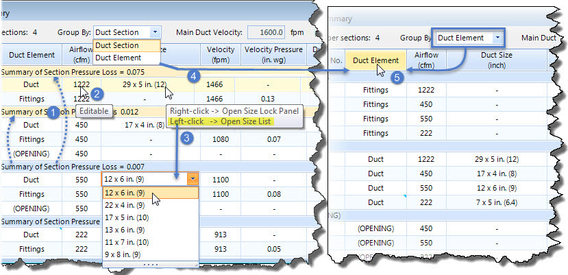
- Editable fields — Values such as for Air Flow, Velocity, Correction Factor, etc., are editable. The mouse hover on it prompts a tool tip "Editable" , and when clicked the cell turns editable.
- Size list — Some of the design values are editable and some selectable from the given list. Mouse hovering over say, on Duct Size prompts a tool tip "Left-click -> Open Size List". Clicking in such cell opens the pull-down list allowing picking a suitable value. Duct size for a rectangular duct follow the format Width x Depth, the value in the bracket indicates equated diameter of equivalent rounded duct. In case of pipe sizing, the size list opens the list of diameters to select suitable one.
- Group By — The option provides sorting the components by Section or by Element. For example; choosing the Duct Element option rearranges the summary table rows by Duct Element: <element>, and the rows display Duct Element: Duct, Duct Element: Fittings, or Duct Element: Opening.
- Sort by elements — When the components are sorted in element the table system arranges the duct elements in groups of equal type fittings, ducts/pipes and openings or fixtures. Clicking in the Duct / Pipe Element column heading toggles the order of duct element listing.
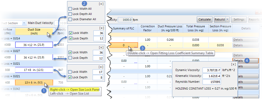
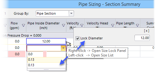
- Size lock — Some Design values can also be locked for keeping them constant in the duct size calculations. Mouse hover on such cell, for example in Duct Size, Velocity, Duct Pressure Loss prompts a tool tip "Right-click -> Open ... Lock Panel". When a right click is pressed it opens the lock panel adjacent to the cell. Checking the Lock keeps that value unchanged in the calculations. The panel is closed using the [X] control in the top right, or the earlier Lock panel closes automatically after another lock panel is opened.
- Lock options — You can selectively lock the value in each row by using the menu on highlighted cell or lock them collectively for all cells in the column (say all ducts sizes in the system) using the right-click on the column heading. For cell values having more than one attribute, the cell boundary effects for the locked value. The cell boundary in the locked field turns in color. You can lock value in one of three fields -Duct Size, Velocity, Duct Pressure Loss. Duct Size for rectangular duct is considered locked when both Width and Depth are locked. The latest locked field will precede past locked field. However, for rectangular ducts where Duct Size was locked for both Width and Length, locking the section for either Velocity or Pressure field would release the Size lock only for Width, keeping the Depth component locked by default. You can manually switch over to lock only Depth, if required. You can alter the value field to a desired dimension and lock it. Values that are locked for calculations are shown with an asterisk ( * ) mark in the report.
- In case of Pipe Sizing, you can lock pipe diameter, velocity, or pipe pressure drop with a right-click in respective cell.
- FLC
table — The mouse hover on
Summary of FLC cells for Fittings prompts a
tool tip "Open Fitting Loss Coefficient Summary
Table", and when double clicked in the
Summary of FLC column, including column
heading opens the Fitting Loss Coefficient Summary dialog.
CLC table — The Component Loss Coefficient Summary table dialog, in case of pipe sizing opens when clicked in the cell in the Summery of Coefficients column of Pipe Sizing dialog.
- Details — The button in the rightmost column opens a pull up panel detailing the values of Viscosities, Reynolds Number and Constant Loss for the selected duct and fittings. The main duct only will have in addition the Holding velocity value displayed. The Reynolds Number for Ducts before calculation displays NaN, and it is replaced with actual value after the calculation. For fittings and openings the Reynolds Number is insignificant and the field is disabled. The values in details are read only data handy for a quick review.
- The Fitting Loss Coefficient Summary dialog lists the summary table based on the Group By option. In addition to Duct Section (1) options, the FLC Summary table can be grouped by Fitting No. (2), Type of Fitting (3), and ASHRAE Fitting No. (4). When grouped by one of these options, the data in corresponding column in the summary table gets sorted when clicked in that column heading.
- Hovering mouse over the fields such as a value in Duct Section prompts a tool tip "Left-click -> Highlight Section Components". Clicking in such cell highlights the component by turning the cell appearance in different color and border.
- The mouse hover on value fields prompts a tool tip "Editable" , and when clicked the cell turns editable.
- The cells in Type of Fitting column (in Fitting Loss Coefficient dialog) can have a comment attached to duct fittings. The opens a Note panel where you can write a desired comment about the duct fitting.