To Create a Grid System
Define buildings and floors to accommodate the new grids system using Defining Stories with Building Floor Manager.
-
Select
 (
Grid Systems
Manager tool) from the Floor Selector toolbox.
(
Grid Systems
Manager tool) from the Floor Selector toolbox.
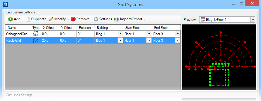
The Grid Systems dialog opens with no grids defined.
-
Select
from the
Grid Systems Settings toolbar.
A default orthogonal grid definition is created.
-
Select
from the
Grid Systems Settings toolbar.
A default radial grid definition is created.
- Select the first floor defined for the building from the Start Floor drop-down, and the last floor definition from the End Floor drop-down for both grids. Leave the Building option with the default setting.
-
Select the orthogonal grid from the
Grid System Settings table.
The Grid Lines Settings table is updated, displaying the Horizontal (U) and Vertical (V) tabs.
-
Activate the
Horizontal (U) tab, and select
Add twice from the
Grid Lines Settings toolbar.
Two new grid lines are added to the end of the Horizontal (U) Grid Lines table.
-
Activate the
Vertical (V) tab, and select
Add twice from the
Grid Lines Settings toolbar.
Two new grid lines are added to the end of the Y grid lines table.
-
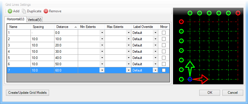
The orthogonal grid is to have uniform spacing for both the
horizontal and vertical grid lines. Enter
10:0 for the
Spacing property on the
Horizontal (U) and
Vertical (V) tabs for all grid lines except
the first grid lines (at origin). Keep those set to
0:0.
As the relative Spacing values are entered, the Distance column is updated listing the cumulative distances between each grid line and the gird origin. The Grid Line Settings table should look like this:
Now complete designing the radial grid:
-
Select the radial grid from the
Grid System Settings grids table.
The Grid Lines Settings table is updated, displaying the Circular Grids and Radial Grids tabs.
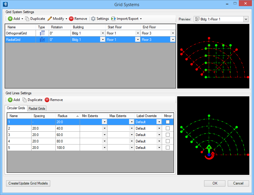
-
Activate the
Radial Grids tab and select
Add from the
Grid Lines Settings toolbar.
The radial grid is now semi-circular.
-
Right click anywhere on the Grid Systems Settings table column
header row, and select
X Offset and
Y Offset.
Enables the X Offset and Y Offset columns on the table.
Note: These settings are disabled by default in favor of using the Grid Systems Orientation controls for offsetting grids. -
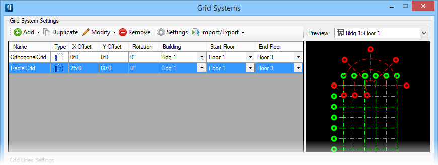
Enter
25:0 for the
X Offset property, and
60:0 for the
Y Offset property.
The origin (center point) of the radial grid is now located at the top/center of the orthogonal grid.
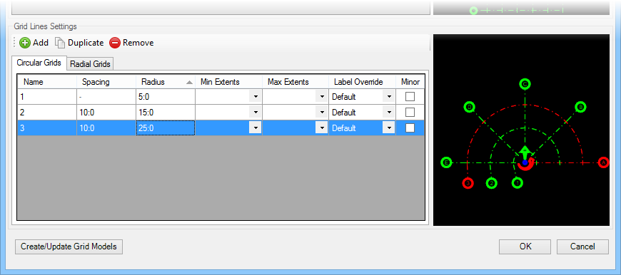
The radial grid line requires the circular grid lines to line up with the orthogonal grid’s six Horizontal (U) grid lines.
- Activate the Circular Grids tab, and select the fourth and fifth circular grid lines. Select Remove from the Grid Lines Settings toolbar.
Now make the changes needed to match the three remaining circular grid lines to the orthogonal grid’s Vertical (V) grid lines:
- Activate the Circular Grids tab and enter 5:0, 15:0 and 25:0 for the Radius property of the three circular grids (1, 2 and 3). Also, ensure to reset the Spacing values to 10 each for two circular grids (2 and 3). The circular grid lines are now aligned with the orthogonal grid’s Y grid lines.
-
Select
OK to save the
grid system.
The Grid Systems dialog closes, and a progress bar indicates the status of the grid system.