| New Layer (icon) |
Adds a new layer to the layers list. By default, an image layer is created. Clicking the down arrow icon opens an option menu for selecting the available map layer items.
- Image — Opens the Open Image File dialog, which is used to select an image file to be added as a layer.
- Gradient — Adds a gradient layer to the layers list box.
- Procedure — Adds a procedural texture layer to the layers list box.
- Operator — Adds an operation layer to the layers list box.
- Texture Replicator — Opens the Open Image File dialog, which is used to select an image to be added as an image mapped texture.
|
| Cut Layer (icon) |
Removes the selected layer from the layers list and copies it to the clipboard. |
| Copy Layer (icon) |
Copies the selected layer to the clipboard. |
| Paste Layer (icon) |
Inserts the layer from the clipboard to the layers list. |
| Delete Layer (icon) |
Removes the layer from the layers list. |
| Name |
Displays the name of the map image file, gradient, procedural texture, or operator, for the layer. |
| Blend |
(Does not apply to Tint or Gamma operators) Click on the Blend value for the required layer and select the required blend option from the menu. Blend defines how the image from a layer is blended with images from layers below it in the Map Editor dialog. The formulae for calculating the resulting pixel for each blend option is based on the following variables:
- pA — Image pixel value of the selected layer.
- pO — Opacity of the selected layer (varies from 0 to 1).
- pB — Image pixel value for the combined layers below the selected layer.
- pR — Resultant (blended) pixel.
- pX — (For Alpha only) Pixel value for the blend between the two images.
- Normal — Takes each pixel from the top layer if present; otherwise, the bottom layer is used. Pixels are blended according to the formula:pR = pO * pA + (1.0 - pO) * pB
Examples:
- If the opacity of the selected layer is 100% (that is, pO = 1.0) then the pixels of image A completely occlude those of the layers below.
- If the opacity of the selected layer is 70% (that is, pO = 0.7) then the resultant pixel color is 70% of image A combined with 30% of image B (the combined image of the layers below).
- Add — Pixels are blended according to the formula:pR = pO * pA + pB
Example:
- If A has 100% opacity, with RGB values 20, 40, 60 and B has RGB values of 100,100,100, then the RGB values for the resulting pixel is 120, 140, 160 — a straight addition.
- Subtract — Pixels are blended according to the formula:pR = pO * pA - pB
Example:
- If A has 100% opacity, with RGB values 100, 100,100 and B has RGB values of 20, 40, 60, then the RGB values for the resulting pixel is 80, 60, 40 — a straight subtraction. Negative values are not allowed. If the subtraction results in a negative value then a value of zero is substituted.
- Alpha — Pixels are blended according to the formula:pR = pO * pA * pX + (1.0 - pO) * (1.0 - pX) * pB
In the list box, the Alpha image is on the same row as the selected layer. pB is the composite of all the images in the background node and pA is the composite of all the images below, but not in the background node.
- Difference — Subtracts the top layer from the bottom layer or the other way round, to always get a positive value. Blending with black produces no change, as values for all colors are 0. The RGB value for black is 0,0,0. Blending with white inverts the picture.
- Normal Multiply — Similar to the Multiply blend mode, this mode multiplies layer A X layer B. However, Normal Multiply goes one step further and "normalizes" the result (taking the square root of the result) to keep the result from darkening too much. For example, if A is 75% and B is 50%, Multiply produces a result of 37.5%, but Normal Multiply results in 61% (square root of 0.375). Normal Multiply is recommended because it maintains the overall brightness of the layers.
- Divide — This blend mode simply divides pixel values of one layer with the other.
- Multiply — This blend mode runs a straight multiplication of the RGB components of the top layer image pixels by the RGB values of pixels in the layer below. If, for instance, where in the image you have a pure blue pixel and multiply with pure green, the result will be black since you are multiplying zero values. Pure blue is 0.0, 0.0, 1.0 and pure green is 0.0, 1.0, 0.0 so when you multiple each component together the result is 0.0, 0.0, 0.0.
- Screen — With Screen blend mode the values of the pixels in the two layers are inverted, multiplied, and then inverted again. This is the opposite of multiply. The result is a brighter picture.
- Overlay — Combines Multiply and Screen blend modes. Light parts of the image become lighter and dark parts become darker.
- Soft Light — This is a softer version of Overlay. Applying pure black or white does not result in pure black or white.
- Hard Light — Combines Multiply and Screen blend modes. As opposed to Overlay, the contrast is also increased.
- Darken — This blend mode takes the darkest value for each pixel from each layer.
- Lighten — This blend mode takes the lightest pixel value from each layer.
- Color Dodge — This decreases the contrast to make the bottom layer reflect the top layer: the brighter the top layer, the more its color affects the bottom layer. Blending with white produces white, blending with black does has no affect on the image.
- Color Burn — This darkens the top layer increasing the contrast to reflect the color of the bottom layer. The darker the bottom layer, the more its color is used. Blending with white produces no difference.
|
| Value |
Sets the value for a layer. To make a change, click on the Value entry for the selected layer. Values settings vary for the different types of layer.
- Image (pattern or bump map) — Click on the image Value setting to open a slider that lets you vary the opacity from zero to 100 percent. Other editable values, for the selected image, display below the layers list box.
- Procedural textures — Click on the procedural textures value setting to open a slider that lets you vary the opacity from zero to 100 percent. Other editable values, for the selected procedural texture, display below the layers list box.
- Gradient — Click on the Gradient Value to open a slider that lets you vary the opacity from zero to 100 percent. Other editable values, for the selected gradient, display below the layers list box.
- Tint (operator) — Click on the color swatch to open a color picker dialog that lets you define a color.
- Gamma (operator) — Click on the Gamma value and enter a new value.
|
| Display |
Click on the Display entry to change the display state of the layer. |
| Map type option menu |
Lets you select the type of file to be used for the map.
- Image — Lets you select an image file, using the Open Image File icon to the right of the option menu and the text field. The name of the selected image file appears in the text field. When you pause the pointer over the name field, the full path name of the image file is displayed in a tooltip. When an image is selected, an expandable mapping section directly below lets you define how the image is mapped.
- Gradient — Lets you select a gradient as a material map. A second option menu on the right lets you choose a Linear or Radial gradient. With the image section expanded, clicking the color key buttons below the gradient display sample, opens the Gradient Color Chooser dialog, which lets you select the colors for the gradient. Clicking on the gradient strip lets you place further color keys to control the gradient. Up to 50 color keys can be assigned to a gradient. See Gradient maps for information on creating gradients.
- Procedure — Lets you select a procedural texture from an option menu on the right. When you pause the pointer over the procedure option menu, the full path name of the procedural file is displayed in a tooltip. With the image section expanded, custom settings for the selected procedural texture appear below the option buttons.
- Operation — Lets you add Tint color or a Gamma value, selected from the option menu to the right. When Tint is selected, clicking the color button below lets you select a color. When Gamma is selected a text field below lets you input values from 0.01 to 3.00.
- Special — Lets you use the "dcdrape" pattern map for image draping.
- Texture Replicator - Lets you procedurally clone an image mapped texture onto a surface while adding some randomization to the resulting clones.
|
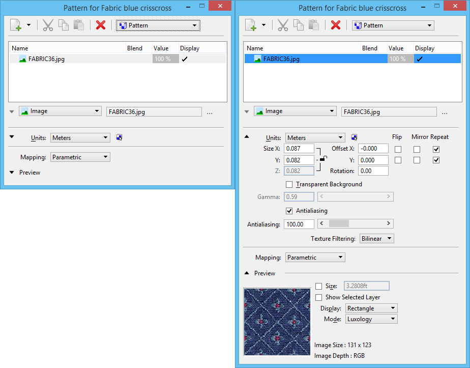
| Mapping section |
The Mapping section lets you define how the map is applied to surfaces in a rendered image. |
| Preview section |
The Preview section displays a sample of the material or a selected layer. |
| Right-click menu |
Right-clicking on a layer entry in the list box lets you perform various functions.
- Cut — (Same function as the Cut Layer icon) Removes the selected layer from the layers list and copies it to the clipboard.
- Copy — (Same function as the Copy Layer icon) Copies the selected layer information to the clipboard.
- Paste — (Same function as the Paste Layer icon) Inserts the layer from the clipboard into the layers list.
- Paste Special — Replaces the currently selected layer information with that in the clipboard.
- Delete — (Same function as the Delete Layer icon) Removes the layer from the layers list.
- Move Up — Moves the selected layer or group up one row in the list box.
- Move Down — Moves the selected layer or group down one row in the list box.
|