Point Light
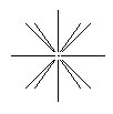
Point Light source cell
|
Similar to a light bulb, light radiates in all directions from a Point Light source. To create a Point Light source, normally you need only define its location. Where an IES lighting file is specified for a Point light source, the direction that light radiates may vary, and you may be required to define a direction.
Note: To ensure that the IES values are applied correctly to the light source, it is recommended that Point Lights be used with IES data. Using Spot Lights or Area Lights can result in restriction of the IES lighting to within the cone of spot lights, or to the front side of area lights.
|
Spot Light
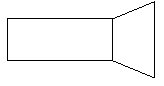
Spot Light source cell
|
Working like a real spot light, settings for the Spot Light sources let you focus the beam (Cone Angle), and the edge fall-off, where the light falls from full intensity to zero (Delta Angle).
To create a Spot Light source, you define the location of the light source, first, and then the target point.
|
Directional Light

Directional light source cell
|
Only the direction of this light source is important. No matter where in the design you create a Directional light source, all surfaces facing that direction are equally illuminated. When using volume lighting effects with directional light, the position of the light source has an affect on how the volume effect appears. In creating a Directional Light source, you define the location of the light source, first, and then its direction.
Directional Lights can be used to act as "fill" lights, providing equal illumination to all faces directed toward them.
|
| Area Light |
Area Light sources are useful for simulating lighting such as that from fluorescent lighting. You can create an Area Light source from any existing convex polygon by defining a (polygonal) shape for the geometry before selecting the Place Light tool with Area Light selected.
Note: Polygons used to create Area Light sources may have any number of vertices, but they must be convex polygons.
During processing, Area Light sources are first converted into triangular-shaped light sources. A rectangular Area Light source, for example, is converted into two triangular light sources, while a pentagon is converted into five triangular light sources, one for each edge.
|
| Sky Opening |
Sky Openings are not true lights in the traditional sense, but act as a control when using Solar lights. Performance is improved by only testing for shadows in the directions of the sky openings, as opposed to testing the entire sky. When using Solar lighting, the light rays are present throughout the model, not just in the vicinity of the design geometry. For efficiency, you can create one or more sky openings that restrict the calculations to the light that passes through the sky opening only. You should use sky openings in particular where you have an interior space illuminated from outside by Solar lighting. For exterior scenes also, you can use sky openings to focus the processing on the region of the model where the design geometry is located.
You place a Sky Opening the same way that you place an Area Light. That is, you first define a (convex polygonal) shape for the geometry. You then select the Place Light tool, select the geometry, then define the direction that the opening shines light. For example, an opening representing a window would point toward the inside of the room (that is, the direction the sunlight travels into the room from the window).
Note:
- Polygons used to create Sky Openings may have any number of vertices, but they must be convex polygons. When there are any Sky Openings in a design, Solar, and Sky light will shine/pass through those openings only, thus reducing the amount of time spent calculating light energy/particles outside the scene.
- Sky Openings apply even when shadows are OFF for the corresponding light. This means that you can model a room with one window, then use Solar and Sky light to illuminate the scene through that window only, without calculating shadows.
- Only objects in front of the sky opening will receive light and, as with a real window, objects outside (behind) the opening can cast shadows through the opening. Also keep in mind that you do not need to create an opening for every pane of a window; you can create a single opening that covers all the panes, or even a group of windows.
|