Source Lighting
MicroStation supports following source lighting types — Directional, Point, Spot, Area, and Sky Openings. Out of which Directional, Point and Spot come in the form of cells delivered in the cell library "lighting.cel." Additionally, you can select from sample predefined light sources in the delivered DGN file "lightlist.dgn" or create your own predefined lights in that or another DGN file. Light source cells have a number of settings that you can adjust to get the correct lighting. For photo-realistic rendering, you can use IES lighting files to set physically correct values for Point, Spot, and Area light source cells.
During rendering, the source lighting cells present in the active file are always considered. Any source lighting cells located in references are ignored unless the Use Lights icon is turned on for the reference in the Attachment Properties dialog. You can open this dialog by selecting in the References dialog.
Light sources present in references (that have Use Lights turned on) can be seen in the Light Name list of the Light Manager dialog. Lights from references are displayed in collapsible lists under the name of each reference. You can view the settings of light source cells in references, but you cannot edit them from the active file.

You can use this feature to experiment with different lighting setups. For example, you can create multiple lighting files to which you can reference your models with Use Lights turned off, so that only the source lighting in the active file is used.
Light sources direct light as follows:
- Directional Light — directional light, producing parallel light rays throughout the model. That is, the light source's orientation defines the direction of uniform light that illuminates all surfaces facing in its direction. This applies whether they are in front of or behind the light source in the model.
- Point Light — light is radiated in all directions from the origin of the light source.
- Spot Light — directional light having a conical beam, similar to a flashlight. Spot light sources having the same Lumens and Intensity settings as a Point light source may appear brighter in rendered images because the energy is restricted to the cone angle.
- Area Light — useful for many diffuse lighting situations, such as simulating fluorescent lighting, where the light source is neither a Point light nor a Spot light. Area light sources are created from existing polygonal shapes in the design.
By default, the delivered light sources all have Bulbs set to 1 and their Lumens value set to 1500.
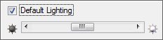
Modeling Lighting — Since modeling lighting provides uniform lighting that remains relative to the eye point, it provides ideal illumination during the modeling phase of any 3D project. This lighting can be used instead of adding scene lighting (Source lights and Global lighting). In order to utilize modeling lighting, you must turn on the view attribute Default Lighting.
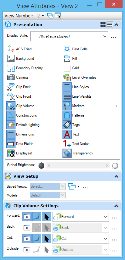
To use modeling lighting with the Render tool, you must enable Default Lighting for the view being rendered. To return to the source lighting setup, Default Lighting must be disabled for the view.
Similarly, where hardware render modes are used to render a view, simply toggling the Default Lighting view attribute option determines the type of lighting used.