MicroStation CONNECT Edition Help

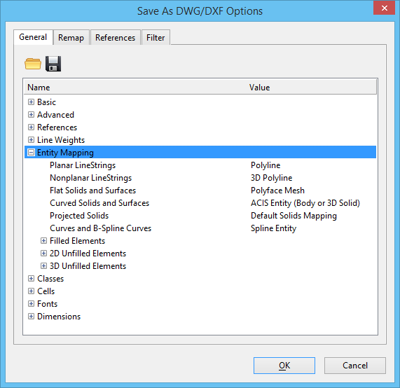
Save As DWG/DXF Options Dialog, General Tab, Entity Mapping

Used to set entity mapping options for saving to DWG and DXF files. Opens when you select File > Save As, select AutoCAD Drawing Files (*.dwg) from the Save as Type list, and click the Options button.

The DGN file format is a superset of the DWG file format. While every DWG entity can be accurately represented in a DGN file, the converse it not true. When saving certain DGN elements to DWG, the geometry types may not match exactly. In this case, the DGN geometry must be converted to an alternate representation that can be saved as a DWG entity. The type of DWG entity that is created is typically dictated by the intended purpose of the DWG file.

Other groups of options under the General tab include:


Save As DWG/DXF Options General tab, Entity Mapping

SettingDescription
Planar LineStrings Sets options for mapping planar line strings.
  • Polyline — (default) A polyline is a 2D entity defined on a plane in space. In general, planar line strings are most efficiently represented by polylines (or lightweight polylines).
  • 3D Polyline — Any planar line string that is not parallel to the XY plane or that has a non-zero elevation is saved to a 3D polyline. This option is for applications that do not work well with lightweight polylines.
Nonplanar LineStrings Sets options for mapping nonplanar line strings.
  • Polyline — This option saves line strings whose vertices are nonplanar by a small deviation to the nearest plane. Such line strings are represented as light weighted polylines. If there is a large coordinate deviation, it indicates that the nonplanarity is by design and hence the mapping is ignored.
  • 3D Polyline — (default) To represent a nonplanar line string with complete accuracy, save it as 3D polylines. However, some applications do not support 3D polylines, and AutoCAD does not display line types on 3D polylines.
Flat Solids and Surfaces Sets options for mapping any surface or solid element with flat (planar) faces.
  • ACIS Entity (Body or 3D Solid) — The complete element representations are converted to 3D Solid entities, and surfaces are converted to Body entities.
  • Polyface Mesh — (default) This efficient representation preserves the appearance of flat solids or surfaces, but not their overall structure. Generally, polyface meshes cannot be edited, and they are not useful for analysis.
  • Wireframe — This option saves only the wireframe geometry, a compact representation of the outline only. A wireframe cannot be rendered.
Curved Solids and Surfaces Sets options for mapping any surface or solid element with curved faces.
  • ACIS Entity (Body or 3D Solid) — (default) The complete element representations are converted to 3D Solid entities, and surfaces are converted to Body entities. This option is highly recommended, since only ACIS entities can accurately represent curved surface or solid elements in AutoCAD.
  • Polyface Mesh — A faceted representation of the surfaces is saved as a polyface mesh. This technique is neither accurate nor efficient, and should be avoided. When polyface meshes are generated, the accuracy of the faceting is controlled by the Polyface Mesh Tolerance setting under Advanced options.
  • Wireframe — This option saves only the wireframe geometry, a compact representation of the outline only. A wireframe cannot be rendered.
Projected Solids Sets options for mapping a projected solid to an ACIS solid or a 2D entity with a thickness that represents the projection length.
Curves and B-Spline Curves Lets you define how curves and B-Spline curves are saved.
  • Spline Entity — Curves and B-Spline curves are saved as spline entities.
  • Polyline — Curves and B-Spline curves are saved as polylines.
Filled Elements, 2D Unfilled Elements, 3D Unfilled Elements Unlike DGN, the DWG format does not have strong support for closed, planar elements. Solid or Face elements are limited to 3– or 4–sided polygons. A polyline can be designated as closed, but closed polygons are not recognized as opaque for rendering. Region entities can accurately represent closed elements, but they rely on the ACIS solid modeling engine, and are, therefore, somewhat inefficient. Additionally, DWG has no support for arbitrary filled areas, but instead relies on separate Solid hatch entities.

For maximum flexibility, entity mapping can be selected for the following types of filled and unfilled elements:

  • 3 or 4 sided polygons
  • 5 or more sided polygons
  • Complex shapes
  • Grouped holes

These element types can be mapped to the entities listed:

  • Polyline (compact, simple to edit, unfilled, no rendering)
  • Polyface Mesh (compact, accurate for polygons only, difficult to edit, renderable)
  • "Solid" Entity (simple, renderable, limited to 3 or 4 sides)
  • "Face" Entity (simple, renderable, limited to 3 or 4 sides)
  • "Region" Entity (heavyweight, difficult to edit, renderable)
  • "Hatch" Entity (heavyweight, difficult to edit, solid hatches are always filled)