Reality Mesh Files Support
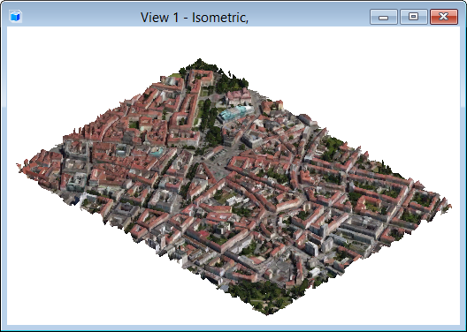
- Fast and accurate display - MicroStation takes advantage of the multiple resolutions within Reality Mesh models to provide fast, accurate display at any zoom level. Efficient use of the Reality Mesh model structure allows even extremely large data sets to be viewed effectively.
- Convenient editing - You can use the familiar MicroStation tools to position and manipulate Reality Mesh models within their current design. MicroStation’s powerful masking and clipping tools can be used to filter the Reality Mesh model display and allow convenient coordination of Reality Mesh data with other design data.
- GeoCoordination - Geographic location data from Reality Mesh models is used to provide accurate and automatic referencing with other data sources.
- Cloud Support - Reality Mesh models can be referenced either locally or from Internet URLs.
Working with Reality Mesh Models
Reality Mesh models consist of many files that are accessed as needed during the display process. The Scene file with extension "3mx" contains the information about the model, including its geographic location (if available) and how to access the model components. The model components are contained in separate files with extension "mx3b". You can directly open or reference Reality Mesh models by selecting the Scene file. The model components (.mx3b) are read internally and must be accessible.
The images within a Reality Mesh model incorporate the lighting that was present when the source images were produced; additional lighting is therefore not required. A display style Unlit Smooth is applied to the Reality Mesh attachment. This causes the Reality Mesh model to ignore the source lighting and instead be displayed at full (as captured) intensity.
- Change Display Styles - Change the display to any predefined display style.
- Apply
Display Rules - Apply display rules to reality mesh and
reality mesh classifiers. Following are some scenarios where display rules can
be used on reality meshes and classifiers:
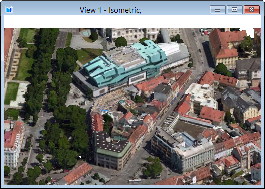
- To differentiate buildings by overriding their symbologies based on their properties, like area, perimeter, or type.
- Color code equipment in a plant, using their maintenance status property. For example, red = maintenance overdue, orange - maintenance due soon, green = maintenance due in over six months.
- Hide all buildings with use or destination property set to commercial in a large reality model.
You can set Hide Element or Symbology Overrides such as color as the action in the display rule.
- Clip - Clip using fences or the Clip Volume tool.

Exporting Reality Mesh Models
As mentioned above, the scene lighting is already captured in the Reality Mesh texture maps; therefore, it will be necessary to view the data with lighting set to maximum brightness in other applications.
Dropping to Mesh Elements
The Application Elements check box in the Drop Element tool can be used to drop a Reality Mesh model to standard MicroStation mesh elements. The Export Resolution property in the Properties dialog controls the size and number of mesh elements created. The mesh images are written to separate JPEG files in the same directory as the active design file.
Printing to 3D PDF
Google Earth Integration
Most Reality Mesh models contain information that indicates their exact geographic location. This allows efficient and accurate integration with other geographic data and applications.
To geographically locate Reality Mesh models, the map or aerial photography can be used as a backdrop by using the Raster Manager with an appropriate geographic aware attachment source (Bing Maps, WMS etc.).
Geographically located Reality Mesh models are suitable for use with the Google Earth integration tools (available from the Geographic group of the Utilities tab in the ribbon bar). When exporting to Google Earth, the exported mesh resolution can be controlled as with other 3D export (like in the 3D PDF, above). These settings are controlled in Google Earth Settings dialog. As Reality Mesh models contain both 3D data and texture maps, KML and Collada should be selected from the Format drop-down options in Google Earth Settings dialog. The Reality Mesh model should also contain correct elevation data, therefore Absolute should be selected from the drop-down options of Altitude Mode and Reproject Elevation check box should be turned on. As Reality Mesh elevation data is usually Geoid based, rather than based from the datum, it may be necessary to change the Vertical Datum setting to Geoid in the Coordinate Systems Modifiers section in Geographic Coordinate System Properties dialog.
Reality Mesh Utility Tools Key-ins
| Key-in | Use |
|---|---|
| MRMESH ATTACH <URL or filename> | Used to attach a Reality Mesh model directly to the current design file. A Reality Mesh model URL or filename can be included as part of the key-in. If none is included then a file open dialog is opened to allow a file to be located interactively. A single data point is required to locate the model origin. |
| MRMESH GEOATTACH <URL or filename> | Used to attach a geographically located Reality Mesh model directly to the current design file. A Reality Mesh model URL or filename can be included as part of the key-in. If none is included then a file open dialog is opened to allow a file to be located interactively. The active model geographic coordinate system will be set to match the geographic system of the Reality Mesh model. |
Reality Mesh Associative Clipping Tools Key-ins
These tools are provided for associating clips to Reality Mesh models. This clipping is derived from the associated clip element geometry directly and modifications to the clipping element are automatically reflected in the clipping of the Reality Mesh model. The clipping can be removed with the MRMESH UNCLIP ELEMENT key-in or by simply deleting the clip element. The clipping can also be disabled by freezing the clip element level. Turning the clip level off without freezing will not affect the clipping.
| Key-in | Use |
|---|---|
| MRMESH CLIP | Used to clip a Reality Mesh model to the interior of the associated element. |
| MRMESH MASK | Used to mask a Reality Mesh model by the associated element. |
| MRMESH SPLIT | Used to split a Reality Mesh model into two separate attachments, one for the interior of the associated element and one for the exterior. |
| MRMESH UNCLIP FENCE | Used to remove all clippings applied to the selected Reality Mesh model through fence clip operations. |
| MRMESH UNCLIP ELEMENT | Used to remove associative clipping applied with the MRMESH CLIP, MRMESH MASK or MRMESH SPLIT key-ins. |