Working with Work Locations
This section contains information about constructing design layouts organized by work locations. Consult the topics in this section for help with creating work locations, assigning features to these locations, and customizing the construction details of these assigned facilities.
About Work Locations
A work location is a place where a facility change is planned at the job site. A design's work locations provide a way of grouping construction details, particularly compatible unit data. Work locations in Bentley OpenUtilities Designer are of two types: points and spans. Point features (such as poles, transformers, and gas meters) are assigned to work points, span features (conductors, gas mains) to work spans (see About Features).
With designs requiring a sketch, Bentley OpenUtilities Designer generates points and spans from the paths, or trails, that you draw in the GIS window by placing trail points. Paths mimic sections of the real-world network and serve as organizers for work location data. During the generation of work locations, Bentley OpenUtilities Designer annotates the points and spans of the GIS drawing and displays a list of these work locations in the Design Workspace.
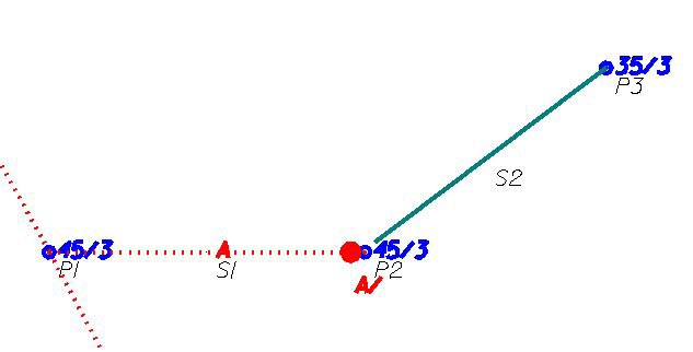
For example, a simple design for an overhead line extension might involve an existing pole and the following new facilities: two poles, a transformer, single-phase primary conductor, and service conductor. If the designer constructs a single path for these facilities, Bentley OpenUtilities Designer would create five work locations-three work points (at the existing pole and at each new pole) and two work spans (the two segments between the three points). The designer would then assign the new facilities to the appropriate work locations.
The Design Assistant provides tools for compiling, organizing, and displaying path information. After paths and work locations are generated, the Features Catalog is used to assign facilities to the various work locations.