Wiring Diagram Settings
Cable Cross-References Tab
The Cable Cross-References tab has settings for diagrams that show cable connection information.
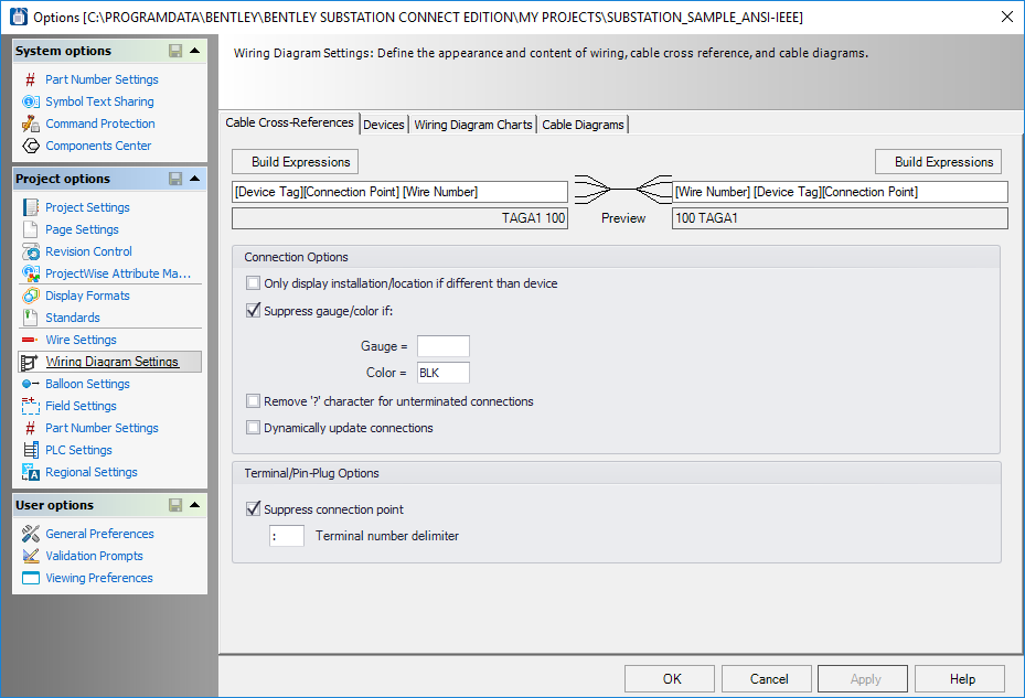
At the top of the dialog is a graphical representation of a cable wiring diagram symbol with fields for defining the connection information on each side of the symbol. To configure the information in these fields, select the Build Expressions button above the desired field and use the Expression Builder dialog to define the settings.
| Setting | Description |
|---|---|
| Only Display Installation/Location if Different Than Device | The installation/location in the connection information will only be displayed if it is a different installation/location than that of the device represented by the symbol. |
| Suppress Gauge/Color If | Allows you to suppress display of gauge and/or color values if the values match those entered in the Gauge and Color fields. |
| Remove `?' Character For Unterminated Connections | When selected, this check box suppresses the question mark character that marks un-terminated connections. |
| Dynamically Update Connections | If you select this check box, connection information on the wiring diagram will be updated automatically each time the page is opened. If the check box is not selected, the page will only be updated when the Update Wiring Diagram function is selected. |
| Suppress Connection Point | When the check box is selected, the connection point designation (I, E) will not be displayed with the terminal number. |
| Terminal Number Delimiter | Defines the character used to separate the terminal block number from the terminal strip name. |
Devices Tab
The Devices tab has settings for wire diagrams that contain standard (non-cable) hardware devices.
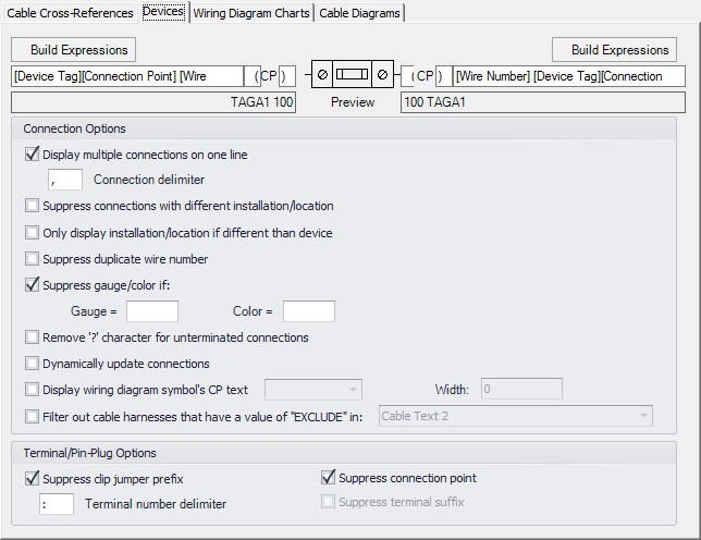
At the top of the dialog is a graphical representation of a wire diagram symbol with fields for defining the connection information on each side of the symbol. To configure the information in these fields, select the Build Expressions button above the desired field and use the Build Expression dialog to define the settings.
| Setting | Description |
|---|---|
| Display Multiple Connections on One Line |
When this check box is checked, connections that have multiple wires will display the information on one line rather than on separate lines. |
| Suppress Connections With Different Installation/Location | Connections that go from/to different installations or locations will be ignored and not included. |
| Only Display Installation/Location if Different Than Device | The installation/location in the connection information will only be displayed if it is a different installation/location than that of the device represented by the symbol. |
| Suppress Duplicate Wire Number | Do not display wire numbers that are duplicates. |
| Suppress Gauge/Color If | Allows you to suppress display of gauge and/or color values if the values match those entered in the Gauge and Color fields. |
| Remove `?' Character For Unterminated Connections | When selected, this check box suppresses the question mark character that marks un-terminated connections. |
| Dynamically Update Connections | If you select this check box, connection information on the wiring diagram will be updated automatically each time the page is opened. If the check box is not selected, the page will only be updated when the Update Wiring Diagram function is selected. |
| Display Wiring Diagram Symbol's CP Text | Select this check box if you wish to have connection point text displayed on the wiring diagram symbol. When you select the check box, a drop-down list becomes active allowing you to select whether the text will be displayed Always or Conditionally. |
| Filter Out Cable Harnesses that Have a Value of "EXCLUDE" in | If you wish to exclude certain cable harnesses from the wiring diagram, you can put the text string EXCLUDE in one of the cable texts for that harness. Then you must select this check box and then select from the drop-down list which cable text includes the EXCLUDE text. |
| Terminal/Pin-Plug Options | These settings affect the display of terminal or pin/plug information. |
| Suppress Clip Jumper Prefix | When selected, the prefix for clip jumpers ("CLIP:") will not be displayed. |
| Terminal Number Delimiter | Defines the character used to separate the terminal block number from the terminal strip name. |
| Suppress Connection Point | When this check box is selected, the connection point designation (I, E) will not be displayed with the terminal number. For example, if the full terminal connection is TB2:01:E, then when this check box is selected it will be displayed as TB2:01. |
| Suppress Terminal Suffix | This check box is only available when you do not select the Suppress Connection Point check box . This is for situations where the terminal number is part of the connection point text and you only wish to remove the "I" or "E"suffix (this usually occurs with legacy projects). For example, if the full terminal connection is TB2:01E, then when you select Suppress Terminal Suffix, it will be displayed as TB2:01. |
Wiring Diagram Charts Tab
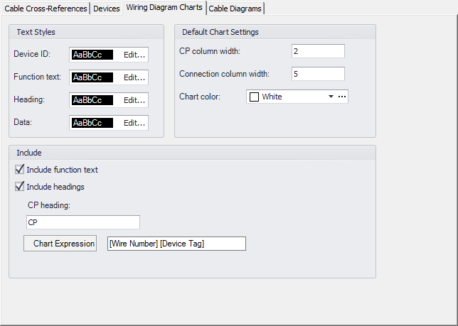
The Wiring Diagram Charts tab has settings for diagrams that show connections in a table format. You have the option of using this format rather than using wiring diagram symbols to represent devices.
| Setting | Description |
|---|---|
| Text Styles | Set the text style for the types of text that appear in the chart. Select the Edit button for a text type to Edit Text Style. |
| Include | |
| Default Chart Settings | Enter width values (in default units) for the CP Column Width (connection point column) and Connection Column Width (connection information column). You can also select the Chart Color, which is the color of the dividing lines in the table. |
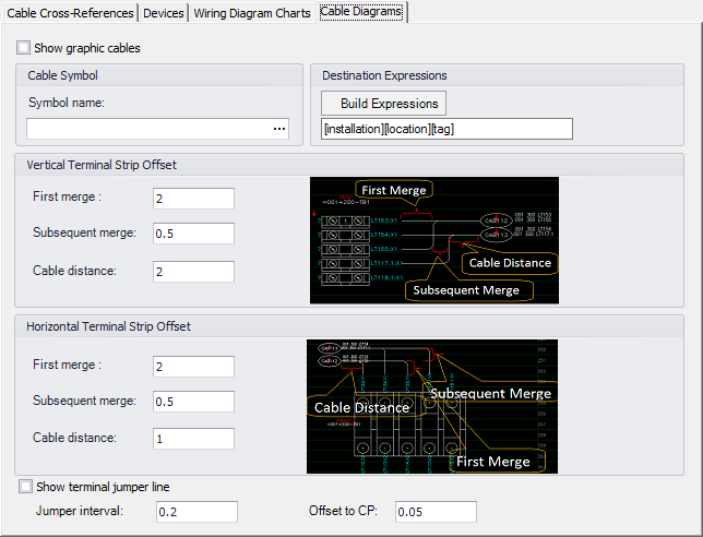
Cable Diagrams Tab
The Cable Diagrams tab has settings that make it possible to automatically draw cables on a wiring diagram page with terminals.
| Setting | Description |
|---|---|
| Show Graphic Cables | Select to enable the automatic cable diagrams. |
| Symbol Name | Use the Browse button to select the desired cable symbol. |
| Destination Expressions | In the this field, create a format for the destination information that will appear at the end of the cable. When you select the Build Expressions button, the Build Expression dialog displays which allows you to select available variables for the Destination expression. |
| Vertical Terminal Strip Offset | Enter spacing values that determine where the cable will be drawn in relation to the vertical terminal strips. The diagrams in the dialog show examples of the First Merge, Subsequent Merge and Cable Distance values. |
| Horizontal Terminal Strip Offset | Enter spacing values that determine where the cable will be drawn in relation to the horizontal terminal strips. The diagrams in the dialog show examples of the First Merge, Subsequent Merge and Cable Distance values. |
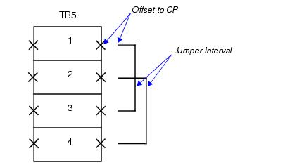
| Show Terminal Jumper Line |
Select this check box if you wish to represent jumpers with a graphical line. The Jumper Interval field allows you to set the spacing between jumpers. The First MergeOffset to CP field allows you to set the distance from the connection point to the end of the jumper. |