Wiring Diagrams Overview
A wiring diagram is a drawing where layout symbols represent devices in the control system. Unlike panel layouts, the software will place connection information beside each layout symbol in the wiring diagram to show what the device is connected to. The connection information comes from the schematic drawings or shortest distance routing. Wiring diagrams are useful for installation and troubleshooting.
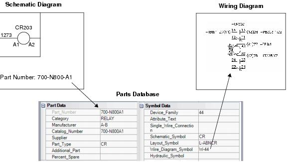
When creating a wiring diagram, you select items from a list of device IDs that have already been used in a schematic drawing. The software knows the part number that was assigned to the device ID. It then uses the information in the parts database to prompt an appropriate wiring diagram symbol for that part.
You can make settings related to wiring diagrams in the Wiring Diagram Settings dialog ( Devices tab).
Wiring Diagram Symbols vs. Wiring Diagram Charts
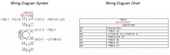
In order to be prompted with a wiring diagram symbol while creating wiring diagrams, you must assign the symbol name in the Wire_Diagram_Symbol field in the parts database records for the parts that you use in your projects. A number of wiring diagram symbols are included with the software. The names of these symbols begin with W-. If you create your own symbols it is recommended that you follow this naming convention, although it is not required. Rather than using wiring diagram symbols, you also have the option of representing devices with wiring diagram charts. These are small tables that show each device's connection information. No symbol creation or parts database editing is required when using wiring diagram charts.
You can make settings related to wiring diagram symbols in the Wiring Diagram Settings dialog ( Devices tab).
You can make settings related to wiring diagram charts in the Wiring Diagram Settings dialog ( Wiring Diagram Charts tab).
General Points About Wiring Diagram Symbols
Wiring diagram symbols are related to the schematic symbols by the connection point text; the wiring diagram connection point must have the same value as the corresponding connection point in the schematic.
Every connection point has a sequence number that uniquely identifies it. The sequence number is defined by the order in which the connection points are inserted in the symbol during symbol creation. Depending upon whether the schematic symbol has a family or not will determine how the wiring diagram function relates the connection points from the schematic to the wiring diagram symbol.
Family Assigned
When there is no family defined the software will simply match the connection point sequence numbers from the schematic symbol with the wiring diagram symbol as shown below:
| Schematic Symbol | Wiring Diagram Symbol | |
|---|---|---|
| Sequence Number | Connection Point | Sequence Number |
| 1 | X1 | 1 |
| 2 | X2 | 2 |
Family Assigned
When a family has been defined we must look at the family definition and how the wiring diagram symbol was created. Within this case there are two possible scenarios depending upon how the user created the wiring diagram symbol:
- The user creates the
wiring diagram symbol with a sufficient number of connection points to handle
all the possible connection points that might exist in the schematic. The user
does not associate any particular role (parent, child, etc.) to these
connection points.
If no role is defined for the wiring diagram connection points, the software identifies the different roles in the family and sorts the connection points in the order that the roles are listed in the family definition. Then it sorts the connection points within each role by their connection point sequence number. The software then matches the first schematic connection point with the first wiring diagram connection point and so on down the line.
- The user creates the
wiring diagram symbol with a sufficient number of connection points to handle
all the possible connection points that might exist in the schematic. The user
associates a role (parent, child, etc.) to each connection point.
The most complicated example of this type would be a family like 2FC for a form C contact configuration. This type of family has alternate symbols defined for it where at least one of the alternate symbols requires three connection points whereas the other symbols only require two connection points. The only way to make sure that the software maps the connection points correctly would be to associate each wiring diagram connection point with a particular role in the family.
In order to handle terminal symbols that have a family associated with them, some special steps are required. When you have a family of terminals you will often have one single wiring diagram symbol that represents several terminal numbers. In this case the user can place multiple terminal number attributes and associate a role with each terminal attribute. This will be used as the common thread to relate the connection points with a particular terminal number attribute.