Run Shortest Distance
This function creates a Bentley Substation connection list that takes into account the physical location of components used on a layout page in order to minimize wire length. This shortest distance connection list is useful to those who do the actual wiring and troubleshooting of the components.
Accessed from:
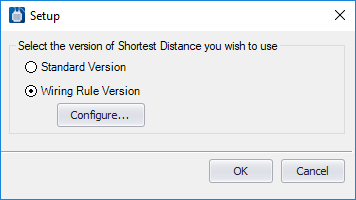
- The Standard Method which uses defined regions for each panel and requires the user to create a region connection diagram to specify the connections from one region to another.
- The Wiring Rules Method which uses an XML file that contains rules for how wires are to be routed between panels. The wiring rules version also permits the user to define cases where additional terminals or plugs should be added to the connection group even though they are not shown in the schematics.
The output from the Shortest Distance Module is an optimized wire list based on the physical layout of components and defined routes between panels that achieves a true shortest distance wire routing scheme. Wire lengths are calculated and provided as a field in the resulting connection list. In addition, the path that each wire takes through the wireways to establish a From-To connection is available for output in a report. The resulting connection list can significantly reduce the time required for the fabrication of the control panel. Also, the information from this list can be graphically reproduced on a termination (wiring) diagram.
| Setting | Description |
|---|---|
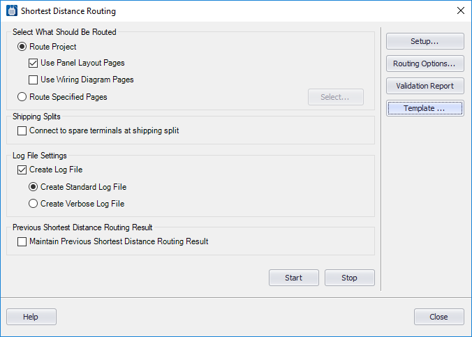
| Route Project |
Select the Route Project option if you wish to include all the panel layout pages in the project in the shortest distance routing. Select whether your routing will be based on Panel Layout Pages or Wiring Diagram Pages. |
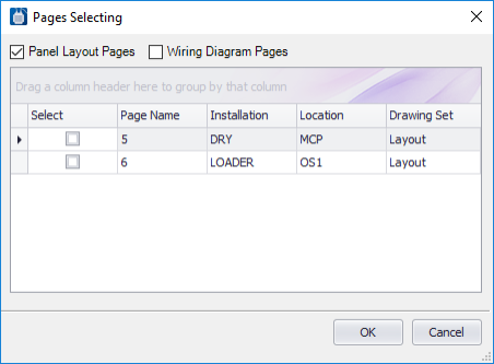
| Route Specified Pages |
Select this option if you wish to limit the routing to selected Panel Layout or Wiring Diagram pages. You can filter the dialog to display either Panel Layout Pages or Wiring Diagram Pages by selecting the desired check box(es). Note: Wiring diagram
pages should only be selected if you are using a legacy project from an older
version of
Bentley Substation
that allowed wiring diagrams to contain layout information.
Select the check box next to the pages to be included and click OK. |
| Shipping Splits | Connect to spare terminals at shipping point: This is the default which displays when the Standard Version option is set in the Setup dialog. Click if there is a shipping split in the panels. (This check box does not appear when you use the Wiring Rules method.) A shipping split requires that connections will be made to spare terminals located on each side of the split before routing through raceways. (These spare terminals are not shown on schematic diagrams. |
| Wiring Rule Settings | The Wiring Rule Settings options display when using
the Wiring Rule Version option set in the Setup dialog. It displays the
following fields:
|
| Create Log File |
Select the check box if you wish to create a log file that records the progress of the shortest distance routing function when it is run. Select the Create Standard Log File option if you wish the log file to contain brief descriptions of each step. Select the Create Verbose Log File option if you wish the log file to contain detailed descriptions of each step. |
| Maintain Previous Shortest Distance Routing Result |
Select this option to keep the previous routing information for all potentials that have not been edited since the last time that shortest distance routing was run. Selecting this will reduce the time it takes to run the shortest distance routing and lessens the chance of an unexpected routing change. |
| Start/Stop | Click Start to begin the Shortest Distance Routing function. Click Stop to abort the procedure. |
| Setup | Displays the
Setup dialog where you can select the
shortest distance method you will be using.
When you select the Wiring Rule Version option, the Configure button is enabled. Click the button to display the Wiring Rules Configuration dialog. |
| Routing Options | Displays the Routing Options dialog to make additional settings for the shortest distance routing function. |
| Validation Report | Displays the most recent Validation Report which is generated when you Start the Run Shortest Distance function. |
| Template | Displays the Template Editor dialog where you can save your settings for the Shortest Distance Routing function. |