To Route Shortest Distance - Wiring Rules Method
The wiring rules version of the Shortest Distance Routing function reads an XML file containing rules that determine how wires are routed between panels. This version is often used by switchgear companies who edit the rules file to suit their particular methods and requirements. These companies typically wire to terminals that are not shown in the electrical schematic diagrams.
The steps for the shortest distance routing function using the wiring rules method are:
- Create a wiring rules XML file that defines how panels or enclosures are to be connected.
-
Create panel layout symbols for panels that include special
attributes for panel name and exit points.
The PanelName attribute prompts for the panel identifier. These names determine the sorting order of panels and are defined in your wiring rules file. If only one panel name will be associated with this layout symbol, enter it in the Default Value field when creating the symbol.
The ExitPoint attribute defines the point(s) where wires leave the panel. Enter exit point coordinates in the Default Value field using the format
x,y;x2,y2
where x,y are the X-Y coordinates of the first exit point and x2,y2 are the coordinates for the second exit point. Separate the coordinates with a semicolon. These coordinates are relative to the insertion point of the panel.
-
Create special panel layout symbols for the extra terminals that
will be placed on the panel layout. These are terminals that do not appear in
the electrical schematics. The software will automatically assign these
terminals for panel-to-panel connections. These symbols must include the
attribute SDWReservedTerminal with an assigned value of SDW. Only terminals
with SDW assigned to this attribute will be assigned automatically by the
Shortest Distance program. (This attribute can be placed anywhere on the symbol
as a "hidden" attribute.)
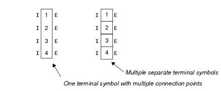
There are two kinds of terminal symbols that you can create to add to the layout. One kind consists of a single layout symbol that represents multiple terminals. You would place multiple terminal number attributes on this symbol in the device ID step of the symbol creation process . On this kind of symbol there must be two connection points for every terminal labeled with the terminal connection designation (such as I or E for internal and external). Alternatively, you can use separate individual symbols for each terminal. This type of symbol would only have one terminal number attribute.
When creating these symbols you must use the same connection point text used by the schematic symbol or family.
- Create electrical schematics with wire connections between components. This allows the software to determine which devices are connected. You must also assign wire numbers to the wires.
-
Create layout diagrams using the special panel layout symbols for
panels and terminals.
- When placing the panel symbols, the device ID will correspond to your naming convention for sections, compartments, etc. For example, the installation name of a panel symbol can represent the name of the section (unit, stack). The location name can represent a compartment within a section, if your designs make use of compartments. You can set this naming convention in the Wiring Rule Configuration dialog.
- If your wiring rules require them, include extra terminals on these layouts that don't exist in the schematics. Use the special terminal symbols you created in step 3. The software will automatically assign these terminals for panel-to-panel connections. These terminals must be placed inside the boundary of a panel (enclosure) symbol.
- Create wire paths on the panel layout. This tells the software where it is permissible to route a wire on a panel. See page 612 for more on creating wire paths.
- If you wish certain wires to be wired directly between devices (i.e., without going through terminals), assign the letter "D" to the wire in the User7 field, see page 651).
- If you wish to group certain wires so that they are forced to connect to spare terminals sequentially, assign the same group number to each wire in the User8 field, see page 652).
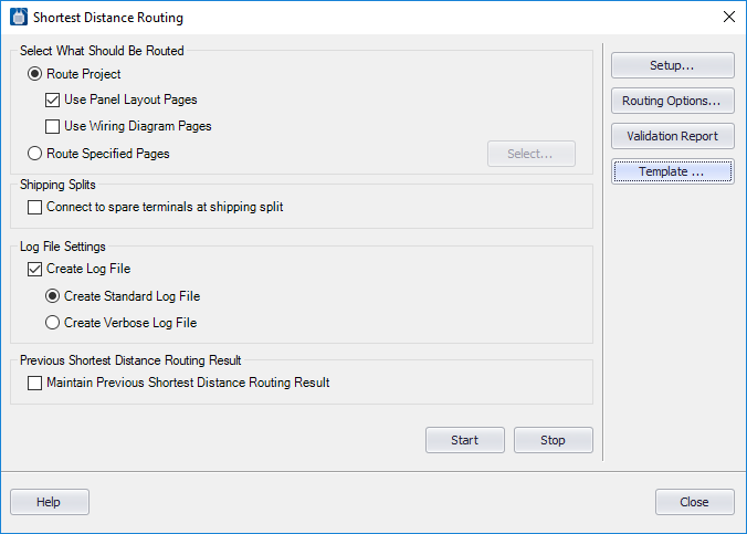
- Next, make settings for the Shortest Distance Routing function. Select the Review/Revise > Run Shortest Distance function. The Shortest Distance Routing dialog displays.
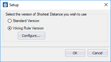
- Select the Setup button to display the following dialog.
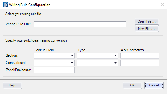
- Select the Wiring Rules Version option and click the Configure button. The Wiring Rules Configuration dialog displays.
- In the Wiring Rule File field, enter the path and name of your wiring rules file.
- Use the remaining fields to define how the Device ID of the panel symbols corresponds to the naming convention for sections and compartments.
- Click OK to save the settings. These are saved in a file named EctRway.xml located in the Shortest Distance directory of the current project.
- Set the remaining fields in the Shortest Distance Routing dialog as desired and click the Start button.
- Run the wire list report to view the shortest distance routing that was created. The wire list contains fields for Route and Length that will be filled in with data from the shortest distance routing function.