To Route the Shortest Distance - Standard Method
- Create electrical schematics with wire connections between components. This allows the software to determine which devices are connected.
- Create a panel layout that defines the spacial relationship between the components. This allows the software to measure the distance between components.
- Create wire paths on the panel layout. This tells the software where it is permissible to route a wire on a panel.
-
Define regions on the panel layout drawing.
A region typically represents a single panel. You might have one region for the items mounted on the door and another region for the items mounted on the back panel. Therefore, by defining regions you are telling the software which items are on the same panel. To create a region on a panel layout page display the desired panel layout page then select the Design > Shortest Distance > Insert Region and define a rectangular region on the drawing by selecting two opposite corner points. This region should enclose all the items that share the same panel, including the panel symbol, if there is one.
The Region Editor dialog will appear. - Define a Region Name, Boundary Coordinates and Exit Points in the dialog and click OK.
- Define the additional regions in the project using the Region Editor as desired. The regions can be on the same layout page or on a different page.
-
Next you must define the connections between regions so that the
software knows how to route wires from panel to panel. Select the
function.
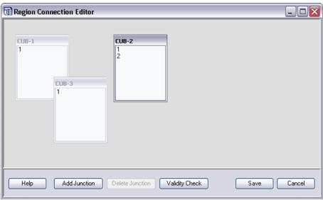
The Region Connection Editor dialog will appear. This
dialog will contain a series of boxes that represent the regions you have
defined. Each box is labeled with the name of the region and the name of the
exit point(s) that you created for that region.
In the dialog, drag each region box to a convenient position for creating connection lines between them (you will be able to re-position the boxes later if necessary).
To create a connection between panels, drag an exit point from one panel to the desired exit point on the next panel. A line will appear between the two exit points. The line represents the route (raceway, conduit, etc.) between the two regions. This line is elastic, so that if you move the region boxes around in the dialog it will stay connected to the two exit points.
- Next, define settings for the Shortest Distance Routing function. Select the Review/Revise > Run Shortest Distance and use the fields in the Shortest Distance Routing dialog to define the settings.
- Click Start in the Run Shortest Distance dialog to begin the routing procedure.
- Run the wire list report to view the shortest distance routing that was created. The wire list contains fields for Route and Length that will be filled in with data from the shortest distance routing function.