Best Practices
Here are a few tips and recommended best practices to use the iTwin Synchronizer efficiently:
- When setting up an iTwin Project, be sure to invite yourself to the connect project. This step allows the iTwin Project to appear from the drop down when selecting the project during Synchronization creation.
- Create an empty iModel on iModelHub at the time of iTwin Project Creation. You will need to have this defined in order to create a Synchronization in the iTwin Synchronizer.
- iModels and synchronization jobs are to be long-lived Digital Twins for the life cycle of the asset. A synchronization should be regularly re-run with small sets of changes to track the history of the project.
- Once a team coordinator creates a synchronization job, each team member should regularly synchronize their own changes to the iModel to create a detailed change history. The more changes that are synchronized, the better the details of the project will be.
- Multiple copies of the same file on different machines are discouraged due to a high risk of causing change conflicts that would be out of synch with the most current changes. Having multiple copies of files require coordination by the Team Coordinator if there is no managed file system in place, such as ProjectWise.
- User must select the master files to be synchronized when creating a synchronization and not select reference files.
- The iTwin Synchronizer can be installed on multiple desktops for teams of users who will be synchronizing their data to the iModelHub.
- It is recommended that synchronizing Design Data to an iModel should be done with files that are stored or located at a common location that can be accessed by all Team Members.
- Please be patient during the first synchronization of the Design Data to the iModel on the iModelHub. Network speeds can greatly affect the time.
For users synchronizing MicroStation DGN files
- If you wish to bridge 3D elements, then the master files must be the files that contain the 3D master models. They should not be sheet models.
- The active view of those master files must be views of the 3D master models. They must not be views of sheets.
- If there are sheets and drawings in other, separate files, they should also be selected as master files. Select the 3D master files and run the bridge. If you don't see all of your sheets and drawings, then select the files that contain them and try again.
For users synchronizing GeoSpatial data
The GeoBridge is being developed to support geospatial data coming from multiple sources.
Presently, the Shapefile format is supported. The support of other geospatial data is under investigation.
SHP File - A shapefile is a format for storing the geometric location and attribute information of geographic features. Geographic features in a shapefile can be represented by points, lines, or polygons (areas).
Configuration File - Geographical elements coming from a Spatial Database don't have any symbolization. To assign symbology to the elements stored in the iModel, a configuration file is required.
The configuration file is also used to specify the Geographic Coordinate System (GCS) of the input file.
The XML configuration files must be in the same folder as the shapefile and have the same name.
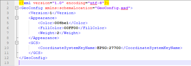
Configuration File definition
- Color - It is the color applied to the point, line and outline (polygon). The color must be specified with Hexadecimal values.
- Fill color - It is the color applied to the interior of polygon. The fill color must be specified with Hexadecimal values.
- Weight - It is the weight applied to the point, line and outline (polygon). The Weight is "value you set + 1 screen pixels (Ex. <Weight>4</Weight> = 4+1=5 pixels).
GCS Section
CoordinateSystemKeyName - It is the coordinate system of the input file. If no GCS is specified in the configuration file, the coordinate system defined in the .prj file will be taken, if no .prj is available, the values in the shp file will be read as is.
Any KeyName available in the GeoCoord dictionary is accepted. If required, the shp file GCS will be reprojected to the iModel GCS. The input file GSC must be reprojectable to the iModel GCS.
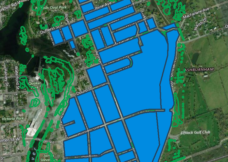
Display Order for Plan Projection (2D)
A lot of GeoSpatial data available in the different industries are in 2D. Most of the GeoSpatial data is at zero elevation. Because of that, a concept of "plan projection model" has been introduced to manage the display order of 2D model in a 3D view.
When processing the GeoBridge on a 2D input file, it is set as a plan projection model. If multiple files are processed in the same iModel, geometries will overlap and cause display issues. This is why it is important to process the files in a specific order to prevent display problems.
The display order is following the order of the input files processed by the GeoBridge. The first file processed will have the lowest priority, the second will be displayed on the top of the first one, and so on.
Example: Process File #1 and Process File #2
If these two files have geometries that overlap, file #2 will appear with a higher priority, thus, on top of file #1.


Also read this article for more information.