Best Practices and Known Limitations
The following list shows recommended best practices and known limitations in this release of Subsurface Utilities CONNECT Edition
Best Practices
It is not recommended to use a global origin shift in subsurface utility DGN files. Doing so results in errors in feature placement location.
It is recommended to keep the size of the Solids Modeling Area (in dgn units) to 1 mile (1 km) or less. This will improve the quality of the utility models and improve results of clash detection throughout.
Whenever possible it is recommended that the total length of a single utility feature be smaller than the size of the solids modeling area. For example, if the Solids Working Area is defined as 1 mile then limit the length of any single conduit to less than 1 mile.
The sample workspaces contain some trench templates as examples for utilities. The templates make use of parametric constraints to adjust the trench for conduit size. These samples assume circular conduit shapes, but could be easily modified for any conduit shape. The samples also assume that the conduit orientation point is along the pipe soffit. Again, this can be easily adjusted for center or invert orientation.

The parametric constraints are applied to the void space for the conduit and also to the width and height of trench.
In this release, the parametric values are not automatically assigned at time of corridor creation. The user can account for pipe size by editing the parametric value after the trench is created.
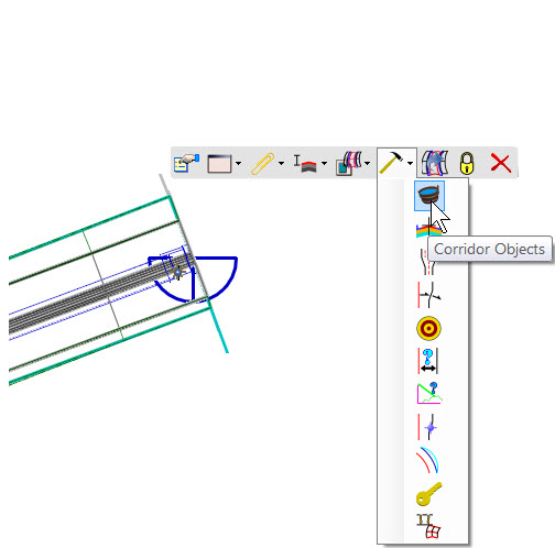
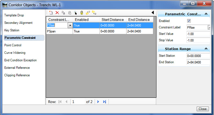
Select the corridor and choose Corridor Objects from the context toolbox.
In the Corridor Object Dialog, add new parametric values for PRise (pipe rise) equal to the negative of pipe rise of the designed conduit.
Note: The variable PRise was used in the samples and is negative because of the orientation of the pipe to template origin. In your own templates, you can use any variable name.
See the OpenRoads corridor documentation for parametric constraints if more information is needed.
The default and recommended minimum merge tolerance is 0.5m (1.5 ft). This value will limit the multitude of found clashes when checking against corridor features. The nature of corridor models results in many clashes close together which this minimum tolerance will limit.
The hydraulic seed data for subsurface utilities hydraulic design is stored in dgn libraries. These libraries can contain storm data, hydraulic settings and various other information used to start a new hydraulic project in your organization. This additional data in dgn libraries adds some extra processing time when starting OpenRoads. Normally, this extra start up time is unnoticeable, but it is possible that very complex hydraulic seed settings could introduce a delay which is undesired, especially to those users who do not perform hydraulic design. If you encounter any objectionable startup delay caused by the hydraulic seed information then it is suggested that you create a separate workspace for those in your organization which do hydraulic design and include the configuration variables only for those hydraulic designers.
- Combine conduit feature definitions and node feature definitions in the same file if you will be utilizing hydraulic seed file.
If you will be making use of a hydraulic seed as described in previous bullet, then the conduit feature definitions and the node feature definitions will need to be combined into a single dgnlib file which also contains the hydraulic seed information. This is because the prototypes which are consumed by feature definition exist in the hydraulic seed, and since there can only be one hydraulic seed then the conduits and nodes feature definitions must reside in the same location.
For inlets, the longitudinal slope for hydraulic calculations can be extracted from the reference surface. The direction of the extracted slope is perpendicular to the orientation line. Thus, the orientation line needs to be drawn perpendicular to any reference alignment or curb that may be expected to be used.
When connecting drainage conduits between nodes, the conduits need to be created from upstream node to downstream node so that proper boundary condition (inlet versus outlet) of headwalls can be determined.
Known Issues
The use of text elements in the cells used for nodes is not supported. Drop the text elements into linear elements.
DGN files which contain a global origin shift will result in 3D models being shifted out of position.
The MicroStation Modify commands are not integrated to function with subsurface utility features. Equivalent functionality to insert vertices, move vertices and insert curves is available in context toolboxes and/or in manipulators.
There is no functionality to change a feature from one type to another type, such as changing from a water type to a gas type. If you need to do this, a technique that you can use is to export the data using ModelBuilder, delete it from the DGN, then import it back again - choosing appropriate feature definitions for the utility type when you do.
The parametric constraint values for the sample trench templates are not automatically defined during trench creation.
If you select multiple conduits (pipes) for bulk editing in Element Information, and those multiple pipes have different feature definitions, the sizes shown in the editing list will include only those in the first selected item.
For example, you select 2 pipes. One of them has a feature definition of Concrete Pipe and the other has a feature definition of Metal Pipe. You wish to change both pipes to feature definition of Plastic Pipe and a certain size.
The original two feature definitions have different sizes of pipes listed in their respective pipe tables. So, when you select the two pipes, the sizes shown in element information will correspond to whichever pipe was selected first.
Your workflow then would be to select both pipes. Then in element information, first change the feature definition to Plastic Pipe. Then change the pipe size.
Alternatively, you may wish to only change the feature definition and have the respective sizes remain the same. Again, select both pipes, then change the feature definition to Plastic Pipe. The sizes of the two pipes will be matched to closest available size available in the new feature definition.
In this release, Subsurface Utilities does not detect clashes with point clouds. Alternative workflow is to use the Clash Detection tool in Bentley Navigator. However, Bentley Navigator does not create conflict nodes.
- Utility Filters > Conduit Filters - the drop down list for conduit sizes may not show the bottom 1 or 2 items in list
In conduit filters you may notice that one or 2 sizes are not shown in the drop down list. Use the arrow keys to scroll down and select these.
When the 2D geometry and 3D utility models both exist in the same DGN model, conflict detection may fail. It is recommended to avoid such a mixed 2D/3D model.
- Network Navigator - In metric units dgn files the zoom to functionality may be zoomed out farther than expected even when picking the 400% zoom factor in the zoom control. The user can type a higher zoom factor directly into the field to accomplish desired zoom effect.
This is a known defect.
- Designed Grate Length versus 3D model - The hydraulic engines can choose from a list of grates in a catalog to select the best design. This applies to hydraulic computations only. The 3D models will not update to reflect the longer grate or inlet opening.
- Headwall features which function as an outfall - In this release, there is a disconnect between the feature definition for a headwall and the hydraulic designation of "Outfall".
In the feature definition the structure type can be set to "Headwall" or "Outfall". Setting feature definition to "Headwall" type is more flexibility and allows you to use the same feature definition for either inlet or outfall boundary conditions. The boundary condition is determined by direction which pipe is created. The disadvantage to this approach is that for some few commands (Flex Tables is one example) these headwalls are not detected as outfalls. In the flex tables example, the headwalls and outfalls are tabulated separately which is indicative of other examples as well.
Alternately, the feature definitions for the headwalls can be defined as "Outfall" structure type. The down side to this approach is that you may need to maintain separate feature definitions for headwalls which are otherwise identical, one for inlets and one for outfalls.
Drainage networks which are created by Subsurface Utility Drainage and Analysis software can be opened and edited by the standalone versions of StormCAD, CivilStorm, SewerCAD and SewerGEMS. In these products when opening a drainage/sewer project choose DGN as file type and select the DGN file and then the DGN model which contains the Subsurface Utilities data. Then the data will be available for edit and design using the standalone interface. Later the same data can be edited using the Subsurface Utilities environment.
There are some known limitations with this workflow. Features whose position is defined by a civil geometry rule will rest their position when reopened in Subsurface Utilities. This is caused because the standalone products are not aware of the rules. For example, a catch basin is created in Subsurface Utilities using a station/offset rule and the rim elevation is ruled to a surface. When opened in the standalone product the user can reposition this catch basin and successfully compute the network based on the new location. But, when opened again in Subsurface Utilities the rule will reevaluate and the catch basin will revert to the former position.
Thus it is recommended that edits made in the standalone products be limited to non-ruled features.
If you extract a utility from a 2D graphic, and use a feature definition for a storm water or sanitary sewer, then the resulting 3D data for the new nodes includes an extra graphic at an incorrect elevation. Select the nodes and apply a different feature definition to resolve this.