M. To define an enclosed zone
To define the boundary of an enclosed load zone, use the following procedure.
-
Either:
The Add New Enclosed Zone Definitions dialog opens.
On the Loading ribbon tab, select the Enclosed Zone tool in the Define Load Systems group.
or
On the Load & Definition dialog, select the entry and then click Add.

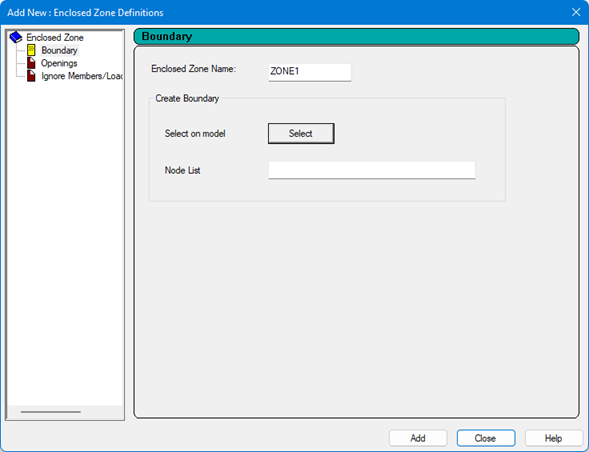
- On the Boundary tab, type a title for the Enclosed Zone Name.
- Define the boundary nodes: The node numbers and coordinates of the boundary vertices are displayed in the dialog table.
- (Optional)
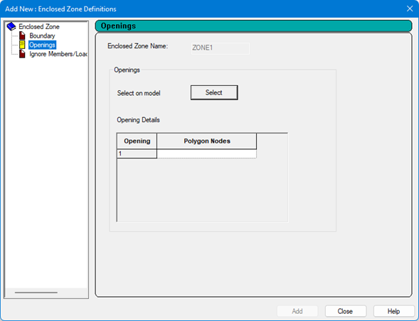
Define any openings within the enclosed zone:
- Select the Openings tab.
- Click Select.
- Click the nodes to form the vertices of the opening within the enclosed zone boundary.
- Click on the initial node to close the opening boundary. The nodes which define the opening are displayed in the Openings table.
- Repeat steps 4b through 4d to add additional openings within this enclosed zone.
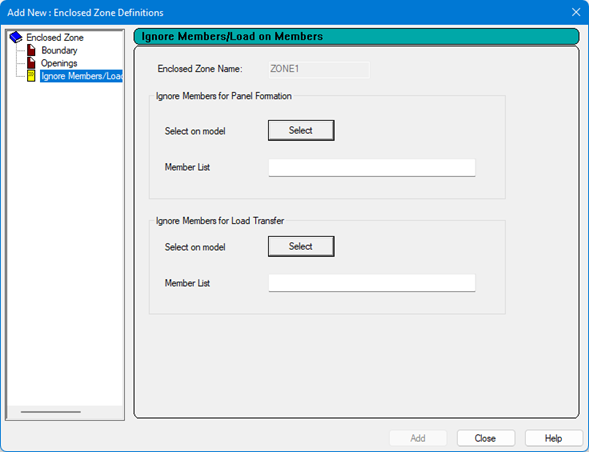
- (Optional) Specify any members which should be ignored when forming the loading panel:
- (Optional) Specify any members which should be ignored for load transfer:
- Click Add.