D8.C.4 Design Parameters
The following table contains the input parameters for specifying values of design variables and selection of design options.
| Parameter Name | Default Value | Description |
|---|---|---|
| CODE | - | Must be specified as IS801
Design code to follow. See TR.48.1 Parameter Specifications. |
|
BEAM |
1.0 |
When this parameter is set to
|
| CAN | 0 | Beam type used for deflection checks:
|
| CB | 0 | Bending coefficient Cb used for bending checks. By default (value of 0), this is calculated by the program. |
| CMY | calculated | Coefficient Cm as per Cl. 6.7 for bending about the member Y axis. See IS:801-1975, 6.7. Used for Combined axial load and bending design. Values range from 0.4 to 1.0. |
| CMZ | calculated | Coefficient Cm as per Cl. 6.7 for bending about the member Z axis. See IS:801-1975, 6.7. Used for Combined axial load and bending design. Values range from 0.4 to 1.0. |
| CWY | 0 |
Specifies whether the cold work of forming strengthening effect should be included in resistance computation. See IS:801-1975, 6.1.1
|
| DFF | 0 | "Deflection length"/ maximum allowable local
deflection.
It is recommended to use DJ1 and DJ2 parameters along with DFF for deflection results. |
| DJ1 | Start Joint of member | Joint No. denoting starting point for calculation of "Deflection Length" (See Note a) |
| DJ2 | End Joint of member | Joint No. denoting end point for calculation of "Deflection Length" (See Note a) |
| FLX | 0 |
Specifies whether the member has torsional-flexural buckling restraints that will in turn determine whether the member is susceptible to flexural-torsional bucking mode. See IS:801-1975, 6.6.1
|
| FU |
450 MPa (4588.72 kg/cm2) |
Ultimate tensile strength of steel in current units. |
| FYLD |
353.04 MPa (3600.0 kg/cm2) |
Yield strength of steel in current units. |
| KX | 1.0 | Effective length factor for torsional buckling. It is a fraction and is unit-less. Values can range from 0.01 (for a column completely prevented from buckling) to any user specified large value. It is used to compute the KL/R ratio for twisting for determining the capacity in axial compression. |
| KY | 1.0 | Effective length factor for overall buckling about the local Y-axis. It is a fraction and is unit-less. Values can range from 0.01 (for a column completely prevented from buckling) to any user specified large value. It is used to compute the KL/R ratio for determining the capacity in axial compression. |
| KZ | 1.0 | Effective length factor for overall buckling in the local Z-axis. It is a fraction and is unit-less. Values can range from 0.01 (for a member completely prevented from buckling) to any user specified large value. It is used to compute the KL/R ratio for determining the capacity in axial compression. |
| LX | Member length | Unbraced length for twisting. It is input in the current units of length. Values can range from 0.01 (for a member completely prevented from torsional buckling) to any user specified large value. It is used to compute the KL/R ratio for twisting for determining the capacity in axial compression. |
| LY | Member length | Effective length for overall buckling in the local Y-axis. It is input in the current units of length. Values can range from 0.01 (for a member completely prevented from buckling) to any user specified large value. It is used to compute the KL/R ratio for determining the capacity in axial compression. |
| LZ | Member length | Effective length for overall buckling in the local Z-axis. It is input in the current units of length. Values can range from 0.01 (for a member completely prevented from buckling) to any user specified large value. It is used to compute the KL/R ratio for determining the capacity in axial compression. |
| NSF | 1.0 | Net section factor for tension members. The net area is calculated as NSF×gross area. |
| RATIO | 1.0 | Permissible ratio of actual to allowable stresses |
| TRACK | 0 |
This parameter is used to control the level of detail in which the design output is reported in the output file. The allowable values are:
|
| TSA | 0 |
Specifies whether transverse web stiffeners have been provided to check for the requirements of IS:801-1975, 5.2.4.
|
| UNL | Member length | Unsupported length (in current units) for calculating the allowable bending stress. |
Notes
-
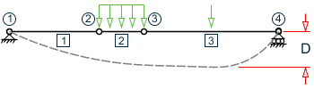
"Deflection Length" is defined as the length that is used for calculation of local deflections within a member. It may be noted that for most cases the "Deflection Length" will be equal to the length of the member. However, in some situations, the "Deflection Length" may be different. A straight line joining DJ1 and DJ2 is used as the reference line from which local deflections are measured.
For example, refer to the figure below where a beam has been modeled using four joints and three members. The "Deflection Length" for all three members will be equal to the total length of the beam in this case. The parameters DJ1 and DJ2 should be used to model this situation. Thus, for all three members here, DJ1 should be 1 and DJ2 should be 4. D = Maximum local deflection for members 1, 2, and 3.PARAMETERS DFF 300. ALL DJ1 1 ALL DJ2 4 ALL