D3.B.6 Design Parameters
Available design parameters to be used in conjunction with BS5950 are listed in table 2B.1 along with their default values.
| Parameter Name | Default Value | Description |
|---|---|---|
| CODE | - |
Must be specified as BS5950 準拠する設計コード。「TR.48.1 パラメータの設定」を参照してください。 |
| AD | Depth at end/2 | Distance between the reference axis and the axis of restraint. See G.2.3 |
| BEAM | 3.0 |
Beam divisions
|
| CAN | 0 |
Deflection check method. See Note 1 below.
|
| CB | 1 |
Specifies the method used to calculate Mb.
|
| DFF | None(Mandatory for deflection check, TRACK 4.0) |
"Deflection Length" / Maxm. allowable local deflection See Note 1d below. |
| DJ1 | Start Jointof member |
Joint No. denoting starting point for calculation of "Deflection Length." See Note 1 below. |
| DJ2 | End Joint of member |
Joint No. denoting end point for calculation of "Deflection Length." See Note 1 below. |
| DMAX * | 100.0cm | Maximum allowable depth |
| DMIN * | 0.0 cm | Minimum allowable depth |
| ESTIFF | 0.0 |
Clauses 4.8.3.3.1 and 4.8.3.3.2
|
| KY | 1.0 | K factor value in local y - axis. Usually, this is the minor axis. |
| KZ | 1.0 | K factor value in local z - axis. Usually, this is the major axis. |
| LEG | 0.0 | Valid range from 0 – 7 and 10-11. The values correspond to table 25 of BS5950 for fastener conditions. See note 2 below. |
| LVV * |
Maximum of Lyy and Lzz(Lyy is a term used by BS5950) |
Used in conjunction with LEG for Lvv as per BS5950 table 25 for double angles. See Note 2 below. |
| LY * | Member Length | Length in local y - axis (current units) to calculate (KY)(LY)/Ryy slenderness ratio. |
| LZ * | Member Length | Length in local z - axis (current units) to calculate (KZ)(LZ)/Rzz slenderness ratio. |
| MLT | 1.0 | Equivalent moment factor for lateral torsional buckling as defined in clause 4.8.3.3.4 |
| MX | 1.0 | Equivalent moment factor for major axis flexural buckling as defined in clause 4.8.3.3.4 |
| MY | 1.0 | Equivalent moment factor for minor axis flexural buckling as defined in clause 4.8.3.3.4 |
| MYX | 1.0 | Equivalent moment factor for minor axis lateral flexural buckling as defined in clause 4.8.3.3.4 |
| NSF | 1.0 | Net section factor for tension members. |
| PNL * | 0.0 |
Transverse stiffener spacing ("a" in Annex H1) 0.0 = Infinity Any other value used in the calculations. |
| PY * | Set according to steel grade (SGR) | Design strength of steel |
| MAIN | 0.0 |
Slenderness limit for members with compression forces, effective length/ radius of gyration, for a given axis:
|
| RATIO | 1.0 | Permissible ratio of the actual capacities. |
| SAME** | 0.0 |
Controls the sections to try during a SELECT process.
|
| SBLT | 0.0 |
Identify Section type for section classification
|
| SWAY | none | Specifies a load case number to provide the sway loading forces in clause 4.8.3.3.4 (See additional notes) |
| SGR | 0.0 |
Steel Grade per BS4360
|
| TB | 0.0 |
LImit of moment capacity in Cl 4.2.5.1: 0 = Mc limit 1.5pyZ 1= Mc limit 1.2 pyZ |
| TRACK | 0.0 |
Output details
|
| UNF | 1.0 | Unsupported length factor applied to the member length for the lateral torsional-buckling effective length per section 4.3.6.7 of BS5950. |
| UNL * | Member Length | Unsupported length for calculating lateral torsional-buckling resistance moment section 4.3.6.7 of BS5950. Given in current length units. |
| WELD |
1.0 closed 2.0 open |
Weld Type
|
* current units must be considered.
**For angles, if the original section is an equal angle, then the selected section will be an equal angle and vice-versa for unequal angles.
D3.B.6.1 Notes
-
CAN, DJ1, and DJ2 – Deflection
-
When performing the deflection check, you can choose between two methods. The first method, defined by a value 0 for the CAN parameter, is based on the local displacement. 局所変位の詳細については、「TR.44 メンバーに関する断面変位の出力」を参照してください。
If the CAN parameter is set to 1, the check will be based on cantilever style deflection. Let (DX1, DY1, DZ1) represent the nodal displacements (in global axes) at the node defined by DJ1 (or in the absence of DJ1, the start node of the member). Similarly, (DX2, DY2, DZ2) represent the deflection values at DJ2 or the end node of the member.
Compute Delta = SQRT((DX2 - DX1)2 + (DY2 - DY1)2 + (DZ2 - DZ1)2)
Compute Length = distance between DJ1 & DJ2 or, between start node and end node, as the case may be.
Then, if CAN is specified a value 1, dff = L/Delta
Ratio due to deflection = DFF/dff
-
If CAN = 0, deflection length is defined as the length that is used for calculation of local deflections within a member. It may be noted that for most cases the "Deflection Length" will be equal to the length of the member. However, in some situations, the "Deflection Length" may be different. A straight line joining DJ1 and DJ2 is used as the reference line from which local deflections are measured.
-
If DJ1 and DJ2 are not used, "Deflection Length" will default to the member length and local deflections will be measured from original member line.
-
It is important to note that unless a DFF value is specified, STAAD will not perform a deflection check. This is in accordance with the fact that there is no default value for DFF.
-
The above parameters may be used in conjunction with other available parameters for steel design.
-
-
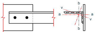
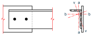
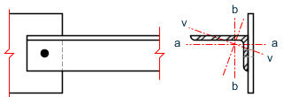
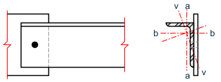
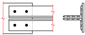
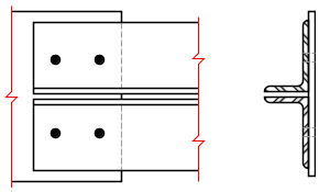
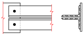
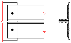
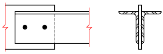
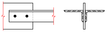
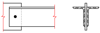
LEGパラメータは、BS5950の表25の要求に従います。この表は、アングル、ダブルアングル、ティー断面、およびチャンネルの細長さに対するファスナ固定条件に関するものです。以下の値が利用可能です。
Table 2. LEGパラメータの値 クローズ ボルト設定 脚 LEGパラメータ 4.7.10.2
シングルアングル
(a) - ボルト2つ 短脚 1 長脚 3 (b) - ボルト1つ 短脚 0 長脚 2 4.7.10.3 ダブルアングル (a) - ボルト2つ 短脚 3 長脚 7 (b) - ボルト1つ 短脚 2 長脚 6 (c) - ボルト2つ 長脚 1 短脚 5 (d) - ボルト1つ 長脚 0 短脚 4 4.7.10.4 チャンネル (a) - 2列以上のボルト 1 (b) - 1列のボルト 0 4.7.10.5 T形断面 (a) - 2列以上のボルト 1 (b) - 1列のボルト 0 シングルアングル、ダブルアングル、チャンネル、およびティー断面の細長さは、メンバー端部に与えられる接合に依存して、BS 5950の表25によって特定されます。適切な接合を定義するためには、LEGパラメータがメンバーに割り当てられる必要があります。
シングルアングルに対しては、細長さは弱軸v-vだけでなく、幾何学的な軸a-aとb-bについても計算されます。幾何学的な軸の有効長さは、以下のように定義されます。La = KY × LY Lb = KZ × LZ v-v軸について計算された細長さは、弱軸(STアングルに対するz-z軸、またはRA設定アングルに対するy-y軸)に対する圧縮強度pcの計算に使用されます。a-aとb-b軸の最大細長さは、強軸に対する圧縮強度pc を計算するのに使用されます。
接合が不明であるか、または表25が適当でないシングルアングルに関しては、代わりにLEGパラメータを10または11にセットすることにより、2つの主軸y-y、z-z軸についてのみ細長さが計算されます。長脚にはLEG 10を使用し、短脚にはLEG 11を使用します。LVVパラメータは使用されません。
ダブルアングルに関しては、表25の注意5に対応するために、LVVパラメータが利用可能です。さらに、ユーザーテーブル(「TR.19.4 ダブルアングル」を参照)からダブルアングルを使用する場合、10個の既存値の最後に、対をなすシングルアングルの回転半径に相当する11番目の値rvvが与えられる必要があります。
-
PY – Steel Design Strength
The design parameter PY should only be used when a uniform design strength for an entire structure or a portion thereof is required. Otherwise the value of PY will be set according to the stipulations of BS5950 table 9 in which the design strength is seen as a function of cross sectional thickness for a particular steel grade (SGR parameter) and particular element considered. Generally speaking this option is not required and the program should be allowed to ascertain the appropriate value.
-
UNL, LY, and LZ – Relevant Effective Length
The values supplied for UNL, LY and LZ should be real numbers greater than zero in current units of length. They are supplied along with or instead of UNF, KY and KZ (which are factors, not lengths) to define lateral torsional buckling and compression effective lengths respectively. Please note that both UNL or UNF and LY or KY values are required even though they are often the same values. The former relates to compression flange restraint for lateral torsional buckling while the latter is the unrestrained buckling length for compression checks.
-
TRACK – Control of Output Formats
When the TRACK parameter is set to 0.0, 1.0, or 2.0, member capacities will be printed in design related output (code check or member selection) in kilonewtons per square meter.
TRACK 4.0 causes the design to carry out a deflection check, usually with a different load list to the main code check. The members that are to be checked must have the parameters DFF, DJ1, and DJ2 set.
-
MX, MY, MYX, and MLT – Equivalent Moment Factors
The values for the equivalent moment factors can either be specified directly by the user as a positive value between 0.4 and 1.0 for MX, MY and MYX and 0.44 and 1.0 for MLT.
The program can be used to calculate the values for the equivalent moment factors by defining the design member with a GROUP command (refer to TR.16.1 グループ設定によるエンティティのリスト). The nodes along the beam can then be defined as the location of restraint points with J settings.
Additionally for the MLT parameter, the joint can be defined as having the upper flange restrained (positive local Y) with the a U setting or the lower flange restrained (negative local Y) with a L setting.
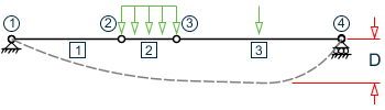
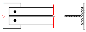
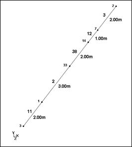
For example, consider a series of 5 beam elements as a single continuous member as shown below:
To enable the steel design, the beam needs to be defined as a group, called MainBeam:
START  GROUP DEFINITION
MEMBER
_MainBeam  11 2 38 12 3
END  GROUP DEFINITION
Therefore, this 5 beam member has 6 joints such that:
- Joint 1 = Node 3
- Joint 2 = Node 1
- Joint 3 = Node 33
- Joint 4 = Node 14
- Joint 5 = Node 7
- Joint 6 = Node 2
-
Consider MX, MY and MYX
Say that this member has been restrained in its’ major axis (local Y) only at the ends. In the minor axis (local Z) it has been restrained at the ends and also at node number 33 (joint 3). For local flexural buckling, it has only been restrained at its ends. Hence:
For the major axis, local Y axis:
MX _MainBeam J1 J6
For the minor axis, local Z axis:
MY _ MainBeam J1 J3 J6
For the lateral flexural buckling, local X axis:
MYX _ MainBeam J1 J6
-
Consider MLT
Say that this member has been restrained at its’ ends against lateral torsional buckling and the top flange has been restrained at node number 33 (joint 3) and only the lower flange at node number 7, (joint 5). Hence:
MLT _MainBeam J1 T3 L5 J6
To split the beam into two buckling lengths for Ly at joint 14:
MY _groupname J1 J4 J6
-
SWAY – Sway Loadcase
This parameter is used to specify a load case that is to be treated as a sway load case in the context of clause 4.8.3.3.4. This load case would be set up to represent the kam pMs mentioned in this clause and the steel design module would add the forces from this load case to the forces of the other load case it is designed for.
Note that the load case specified with this parameter will not be designed as a separate load case. The following is the correct syntax for the parameter:
Parameter Name Default Value Description SWAY (load case number) ALL
MEMBER (member list)
_(group name)
Example
SWAY  5 MEM 1 to 10
SWAY  6 _MainBeams