D8.C.4 Design Parameters
The following table contains the input parameters for specifying values of design variables and selection of design options.
| Parameter Name | Default Value | Description |
|---|---|---|
| CODE | - | Must be specified as IS801
準拠する設計コード。「TR.48.1 パラメータの設定」を参照してください。 |
|
BEAM |
1.0 |
When this parameter is set to
|
| CAN | 0 | Beam type used for deflection checks:
|
| CB | 0 | Bending coefficient Cb used for bending checks. By default (value of 0), this is calculated by the program. |
| CMY | calculated | Coefficient Cm as per Cl. 6.7 for bending about the member Y axis. See IS:801-1975, 6.7. Used for Combined axial load and bending design. Values range from 0.4 to 1.0. |
| CMZ | calculated | Coefficient Cm as per Cl. 6.7 for bending about the member Z axis. See IS:801-1975, 6.7. Used for Combined axial load and bending design. Values range from 0.4 to 1.0. |
| CWY | 0 |
Specifies whether the cold work of forming strengthening effect should be included in resistance computation. See IS:801-1975, 6.1.1
|
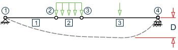
| DFF | 0 | "Deflection length"/ maximum allowable local
deflection.
It is recommended to use DJ1 and DJ2 parameters along with DFF for deflection results. |
| DJ1 | Start Joint of member | Joint No. denoting starting point for calculation of "Deflection Length" (See Note a) |
| DJ2 | End Joint of member | Joint No. denoting end point for calculation of "Deflection Length" (See Note a) |
| FLX | 0 |
Specifies whether the member has torsional-flexural buckling restraints that will in turn determine whether the member is susceptible to flexural-torsional bucking mode. See IS:801-1975, 6.6.1
|
| FU |
450 MPa (4588.72 kg/cm2) |
Ultimate tensile strength of steel in current units. |
| FYLD |
353.04 MPa (3600.0 kg/cm2) |
Yield strength of steel in current units. |
| KX | 1.0 | Effective length factor for torsional buckling. It is a fraction and is unit-less. Values can range from 0.01 (for a column completely prevented from buckling) to any user specified large value. It is used to compute the KL/R ratio for twisting for determining the capacity in axial compression. |
| KY | 1.0 | Effective length factor for overall buckling about the local Y-axis. It is a fraction and is unit-less. Values can range from 0.01 (for a column completely prevented from buckling) to any user specified large value. It is used to compute the KL/R ratio for determining the capacity in axial compression. |
| KZ | 1.0 | Effective length factor for overall buckling in the local Z-axis. It is a fraction and is unit-less. Values can range from 0.01 (for a member completely prevented from buckling) to any user specified large value. It is used to compute the KL/R ratio for determining the capacity in axial compression. |
| LX | Member length | Unbraced length for twisting. It is input in the current units of length. Values can range from 0.01 (for a member completely prevented from torsional buckling) to any user specified large value. It is used to compute the KL/R ratio for twisting for determining the capacity in axial compression. |
| LY | Member length | Effective length for overall buckling in the local Y-axis. It is input in the current units of length. Values can range from 0.01 (for a member completely prevented from buckling) to any user specified large value. It is used to compute the KL/R ratio for determining the capacity in axial compression. |
| LZ | Member length | Effective length for overall buckling in the local Z-axis. It is input in the current units of length. Values can range from 0.01 (for a member completely prevented from buckling) to any user specified large value. It is used to compute the KL/R ratio for determining the capacity in axial compression. |
| NSF | 1.0 | Net section factor for tension members. The net area is calculated as NSF×gross area. |
| RATIO | 1.0 | Permissible ratio of actual to allowable stresses |
| TRACK | 0 |
This parameter is used to control the level of detail in which the design output is reported in the output file. The allowable values are:
|
| TSA | 0 |
Specifies whether transverse web stiffeners have been provided to check for the requirements of IS:801-1975, 5.2.4.
|
| UNL | Member length | Unsupported length (in current units) for calculating the allowable bending stress. |
Notes
-
"Deflection Length" is defined as the length that is used for calculation of local deflections within a member. It may be noted that for most cases the "Deflection Length" will be equal to the length of the member. However, in some situations, the "Deflection Length" may be different. A straight line joining DJ1 and DJ2 is used as the reference line from which local deflections are measured.