EX. US-27 Modeling Soil Springs for a Slab on Grade
This example illustrates the usage of commands necessary to apply the compression only attribute to spring supports for a slab on grade. The spring supports themselves are generated utilizing the built-in support generation facility. The slab is subjected to pressure and overturning loading. A tension/compression only analysis of the structure is performed.
This problem is installed with the program by default to C:\Users\Public\Public Documents\STAAD.Pro CONNECT Edition\Samples\Sample Models\US\US-27 Modeling Soil Springs for a Slab on Grade.STD when you install the program.
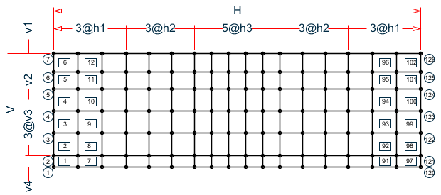
The numbers shown in the diagram below are the element numbers.
    STAAD SPACE SLAB ON GRADE
    * SPRING COMPRESSION EXAMPLE
Every STAAD input file has to begin with the word STAAD. The word SPACE signifies that the structure is a space frame and the geometry is defined through X, Y, and Z axes. An optional title to identify this project is provided in the second line.
SET NL 3
This structure has to be analyzed for 3 primary load cases. Consequently, the modeling of our problem requires us to define 3 sets of data, with each set containing a load case and an associated analysis command. Also, the supports which get switched off in the analysis for any load case have to be restored for the analysis for the subsequent load case. To accommodate these requirements, it is necessary to have 2 commands: SET NL and CHANGE. The SET NL command is used above to indicate the total number of primary load cases that the file contains. The CHANGE command will come in later (after the PERFORM ANALYSIS command).
    UNIT FEET KIP
    JOINT COORDINATES
    1 0.0 0.0 40.0
    2 0.0 0.0 36.0
    3 0.0 0.0 28.167
    4 0.0 0.0 20.333
    5 0.0 0.0 12.5
    6 0.0 0.0 6.5
    7 0.0 0.0 0.0
    REPEAT ALL 3 8.5 0.0 0.0
    REPEAT 3 8.0 0.0 0.0
    REPEAT 5 6.0 0.0 0.0
    REPEAT 3 8.0 0.0 0.0
    REPEAT 3 8.5 0.0 0.0
For joints 1 through 7, the joint number followed by the X, Y and Z coordinates are specified above. The coordinates of these joints is used as a basis for generating 21 more joints by incrementing the X coordinate of each of these 7 joints by 8.5 feet, 3 times. REPEAT commands are used to generate the remaining joints of the structure. The results of the generation may be visually verified using the STAAD graphical viewing facilities.
    ELEMENT INCIDENCES
    1 1 8 9 2 TO 6
    REPEAT 16 6 7
The incidences of element number 1 is defined and this data is used as a basis for generating the 2nd through the 6th element. The incidence pattern of the first 6 elements is then used to generate the incidences of 96 more elements using the REPEAT command.
    UNIT INCH
    ELEMENT PROPERTIES
    1 TO 102 TH 8.0
The thickness of elements 1 to 102 is specified as 8.0 inches following the command ELEMENT PROPERTIES.
    DEFINE MATERIAL START
    ISOTROPIC CONCRETE
    E 4000.0
    POISSON 0.12
    DENSITY 8.68e-005
    ALPHA 5e-006
    DAMP 0.05
    G 1346.15
    TYPE CONCRETE
    STRENGTH FCU 4
    END DEFINE MATERIAL
    CONSTANTS
    MATERIAL CONCRETE ALL
The modulus of elasticity (E) and Poisson’s Ratio are specified following the command CONSTANTS.
    SPRING COMPRESSION
    1 TO 126 KFY
The above two lines declare the spring supports at nodes 1 to 126 as having the compression-only attribute. The supports themselves are being generated later (see the ELASTIC MAT command which appears later).
    UNIT FEET
    SUPPORTS
    1 TO 126 ELASTIC MAT DIRECTION Y SUBGRADE 12.0
The above command is used to instruct STAAD to generate supports with compression-only springs which are effective in the global Y direction. These springs are located at nodes 1 to 126. The subgrade reaction of the soil is specified as 12 kip/cu.ft. The program will determine the area under the influence of each joint and multiply the influence area by the subgrade reaction to arrive at the spring stiffness for the "FY" degree of freedom at the joint. Units for length are changed to FEET to facilitate the input of subgrade reaction of soil. See TR.27.3 Automatic Spring Support Generator for Foundations .
    LOAD 1 'WEIGHT OF MAT & EARTH'
    ELEMENT LOAD
    1 TO 102 PR GY -1.50
The above data describe a static load case. A pressure load of 1.50 kip/ft acting in the negative global Y direction is applied on all the elements.
    PERFORM ANALYSIS PRINT STATICS CHECK
    CHANGE
Tension/compression cases must each be followed by PERFORM ANALYSIS and CHANGE commands. The CHANGE command restores the original structure to prepare it for the analysis for the next primary load case.
    LOAD 2 'COLUMN LOAD-DL+LL'
    JOINT LOADS
    1 2  FY -217.
    8 9  FY -109.
    5    FY -308.7
    6    FY -617.4
    22 23 FY -410.
    29 30 FY -205.
    26   FY -542.7
    27   FY -1085.4
    43 44 50 51 71 72 78 79 FY -307.5
    47 54 82   FY -264.2
    48 55 76 83 FY -528.3
    92 93      FY -205.0
    99 100     FY -410.0
    103        FY -487.0
    104        FY -974.0
    113 114    FY -109.0
    120 121    FY -217.0
    124        FY -273.3
    FY -546.6
    PERFORM ANALYSIS PRINT STATICS CHECK
    CHANGE
Load case 2 consists of several joint loads acting in the negative global Y direction. This is followed by another ANALYSIS command. The CHANGE command restores the original structure once again for the forthcoming load case.
    LOAD 3 'COLUMN OVERTURNING LOAD'
    ELEMENT LOAD
    1 TO 102 PR GY -1.50
    JOINT LOADS
    1 2  FY -100.
    8 9  FY -50.
    5    FY -150.7
    6    FY -310.4
    22 23 FY -205.
    29 30 FY -102.
    26   FY -271.7
    27    FY -542.4
    43 44 50 51 71 72 78 79 FY -153.5
    47 54 82   FY -132.2
    48 55 76 83 FY -264.3
    92 93      FY 102.0
    99 100     FY 205.0
    103        FY 243.0
    104        FY 487.0
    113 114    FY 54.0
    120 121    FY 108.0
    124        FY 136.3
    125        FY 273.6
    PERFORM ANALYSIS PRINT STATICS CHECK
Load case 3 consists of several joint loads acting in the upward direction at one end and downward on the other end to apply an overturning moment that will lift off one end. The CHANGE command is not needed after the last analysis.
    LOAD LIST 3
    PRINT JOINT DISPLACEMENTS LIST 113 114 120 121
    PRINT ELEMENT STRESSES LIST 34 67
    PRINT SUPPORT REACTIONS LIST 5 6 12 13
A list of joint displacements, element stresses for elements 34 and 67, and support reactions at a list of joints for load case 3, are obtained with the help of the above commands.
FINISH
The STAAD run is terminated.
Input File
STAAD SPACE SLAB ON GRADE
* SPRING COMPRESSION EXAMPLE
SET NL 3
UNIT FEET KIP
JOINT COORDINATES
1 0.0 0.0 40.0
2 0.0 0.0 36.0
3 0.0 0.0 28.167
4 0.0 0.0 20.333
5 0.0 0.0 12.5
6 0.0 0.0  6.5
7 0.0 0.0  0.0
REPEAT ALL 3 8.5 0.0 0.0
REPEAT 3 8.0 0.0 0.0
REPEAT 5 6.0 0.0 0.0
REPEAT 3 8.0 0.0 0.0
REPEAT 3 8.5 0.0 0.0
ELEMENT INCIDENCES
1 1 8 9 2 TO 6
REPEAT 16 6 7
UNIT INCH
ELEMENT PROPERTIES
1 TO 102 TH 8.0
DEFINE MATERIAL START
ISOTROPIC CONCRETE
E 4000.0
POISSON 0.12
DENSITY 8.68e-005
ALPHA 5e-006
DAMP 0.05
G 1346.15
TYPE CONCRETE
STRENGTH FCU 4
END DEFINE MATERIAL
CONSTANTS
MATERIAL CONCRETE ALL
SPRING COMPRESSION
1 TO 126 KFY
UNIT FEET
SUPPORTS
1 TO 126  ELASTIC MAT DIRECTION Y SUBGRADE 12.0
LOAD 1 'WEIGHT OF MAT & EARTH'
ELEMENT LOAD
1 TO 102 PR GY -1.50
PERFORM ANALYSIS PRINT STATICS CHECK
CHANGE
LOAD 2 'COLUMN LOAD-DL+LL'
JOINT LOADS
1 2   FY -217.
8 9   FY -109.
5     FY -308.7
6     FY -617.4
22 23 FY -410.
29 30 FY -205.
26    FY -542.7
27    FY -1085.4
43 44 50 51 71 72 78 79 FY -307.5
47 54 82    FY -264.2
48 55 76 83 FY -528.3
92 93       FY -205.0
99 100      FY -410.0
103         FY -487.0
104         FY -974.0
113 114     FY -109.0
120 121     FY -217.0
124         FY -273.3
125         FY -546.6
PERFORM ANALYSIS PRINT STATICS CHECK
CHANGE
LOAD 3 'COLUMN OVERTURNING LOAD'
ELEMENT LOAD
1 TO 102 PR GY -1.50
JOINT LOADS
1 2   FY -100.
8 9   FY -50.
5     FY -150.7
6     FY -310.4
22 23 FY -205.
29 30 FY -102.
26    FY -271.7
27    FY -542.4
43 44 50 51 71 72 78 79 FY -153.5
47 54 82    FY -132.2
48 55 76 83 FY -264.3
92 93       FY 102.0
99 100      FY 205.0
103         FY 243.0
104         FY 487.0
113 114     FY 54.0
120 121     FY 108.0
124         FY 136.3
125         FY 273.6
PERFORM ANALYSIS PRINT STATICS CHECK
LOAD LIST 3
PRINT JOINT DISPLACEMENTS LIST 113 114 120 121
PRINT ELEMENT STRESSES LIST 34 67
PRINT SUPPORT REACTIONS LIST 5 6 12 13
FINISH
STAAD Output File
                                                                  PAGE NO.    1
             ****************************************************
             *                                                  *
             *           STAAD.Pro CONNECT Edition              *
             *           Version  22.12.00.***                  *
             *           Proprietary Program of                 *
             *           Bentley Systems, Inc.                  *
             *           Date=    OCT 27, 2022                  *
             *           Time=    15: 9:53                      *
             *                                                  *
             *  Licensed to: Bentley Systems Inc                *
             ****************************************************
     1. STAAD SPACE SLAB ON GRADE
INPUT FILE: US-27 Modeling Soil Springs for a Slab on Grade.STD
     2. * SPRING COMPRESSION EXAMPLE
     3. SET NL 3
     4. UNIT FEET KIP
     5. JOINT COORDINATES
     6. 1 0.0 0.0 40.0
     7. 2 0.0 0.0 36.0
     8. 3 0.0 0.0 28.167
     9. 4 0.0 0.0 20.333
    10. 5 0.0 0.0 12.5
    11. 6 0.0 0.0  6.5
    12. 7 0.0 0.0  0.0
    13. REPEAT ALL 3 8.5 0.0 0.0
    14. REPEAT 3 8.0 0.0 0.0
    15. REPEAT 5 6.0 0.0 0.0
    16. REPEAT 3 8.0 0.0 0.0
    17. REPEAT 3 8.5 0.0 0.0
    18. ELEMENT INCIDENCES
    19. 1 1 8 9 2 TO 6
    20. REPEAT 16 6 7
    21. UNIT INCH
    22. ELEMENT PROPERTIES
    23. 1 TO 102 TH 8.0
    24. DEFINE MATERIAL START
    25. ISOTROPIC CONCRETE
    26. E 4000.0
    27. POISSON 0.12
    28. DENSITY 8.68E-005
    29. ALPHA 5E-006
    30. DAMP 0.05
    31. G 1346.15
    32. TYPE CONCRETE
    33. STRENGTH FCU 4
    34. END DEFINE MATERIAL
    35. CONSTANTS
    36. MATERIAL CONCRETE ALL
    37. SPRING COMPRESSION
    38. 1 TO 126 KFY
      SLAB ON GRADE                                            -- PAGE NO.    2
    * SPRING COMPRESSION EXAMPLE
    39. UNIT FEET
    40. SUPPORTS
    41. 1 TO 126  ELASTIC MAT DIRECTION Y SUBGRADE 12.0
    42. LOAD 1 'WEIGHT OF MAT & EARTH'
    43. ELEMENT LOAD
    44. 1 TO 102 PR GY -1.50
    45. PERFORM ANALYSIS PRINT STATICS CHECK
            P R O B L E M   S T A T I S T I C S
            -----------------------------------
     NUMBER OF JOINTS        126  NUMBER OF MEMBERS       0
     NUMBER OF PLATES        102  NUMBER OF SOLIDS        0
     NUMBER OF SURFACES        0  NUMBER OF SUPPORTS    126
           Using 64-bit analysis engine.
           SOLVER USED IS THE IN-CORE ADVANCED MATH SOLVER
   TOTAL      PRIMARY LOAD CASES =     1, TOTAL DEGREES OF FREEDOM =     378
   TOTAL LOAD COMBINATION  CASES =     0  SO FAR.
      SLAB ON GRADE                                            -- PAGE NO.    3
    * SPRING COMPRESSION EXAMPLE
  **NOTE-Tension/Compression converged after  1 iterations, Case=    1
          STATIC LOAD/REACTION/EQUILIBRIUM SUMMARY FOR CASE NO.     1
          'WEIGHT OF MAT & EARTH'
           CENTER OF FORCE BASED ON Y FORCES ONLY (FEET).
         (FORCES IN NON-GLOBAL DIRECTIONS WILL INVALIDATE RESULTS)
                        X =  0.645000019E+02
                        Y =  0.000000000E+00
                        Z =  0.200000006E+02
 TOTAL APPLIED LOAD     1
   ***TOTAL APPLIED LOAD ( KIP  FEET ) SUMMARY (LOADING     1 )
       SUMMATION FORCE-X =           0.00
       SUMMATION FORCE-Y =       -7740.00
       SUMMATION FORCE-Z =           0.00
      SUMMATION OF MOMENTS AROUND THE ORIGIN-
      MX=      154800.01  MY=           0.00  MZ=     -499230.03
 TOTAL REACTION LOAD    1
   ***TOTAL REACTION LOAD( KIP  FEET ) SUMMARY (LOADING     1 )
       SUMMATION FORCE-X =           0.00
       SUMMATION FORCE-Y =        7740.00
       SUMMATION FORCE-Z =           0.00
      SUMMATION OF MOMENTS AROUND THE ORIGIN-
      MX=     -154800.01  MY=           0.00  MZ=      499230.03
   MAXIMUM DISPLACEMENTS ( INCH /RADIANS) (LOADING      1)
             MAXIMUMS    AT NODE
      X =  0.00000E+00       0
      Y = -1.50000E+00       1
      Z =  0.00000E+00       0
      RX=  9.79653E-10     121
      RY=  0.00000E+00       0
      RZ=  4.32018E-10      45
   ************ END OF DATA FROM INTERNAL STORAGE ************
    46. CHANGE
    47. LOAD 2 'COLUMN LOAD-DL+LL'
    48. JOINT LOADS
    49. 1 2   FY -217.
    50. 8 9   FY -109.
    51. 5     FY -308.7
    52. 6     FY -617.4
    53. 22 23 FY -410.
    54. 29 30 FY -205.
      SLAB ON GRADE                                            -- PAGE NO.    4
    * SPRING COMPRESSION EXAMPLE
    55. 26    FY -542.7
    56. 27    FY -1085.4
    57. 43 44 50 51 71 72 78 79 FY -307.5
    58. 47 54 82    FY -264.2
    59. 48 55 76 83 FY -528.3
    60. 92 93       FY -205.0
    61. 99 100      FY -410.0
    62. 103         FY -487.0
    63. 104         FY -974.0
    64. 113 114     FY -109.0
    65. 120 121     FY -217.0
    66. 124         FY -273.3
    67. 125         FY -546.6
    68. PERFORM ANALYSIS PRINT STATICS CHECK
      SLAB ON GRADE                                            -- PAGE NO.    5
    * SPRING COMPRESSION EXAMPLE
  **NOTE-Tension/Compression converged after  1 iterations, Case=    2
          STATIC LOAD/REACTION/EQUILIBRIUM SUMMARY FOR CASE NO.     2
          'COLUMN LOAD-DL+LL'
           CENTER OF FORCE BASED ON Y FORCES ONLY (FEET).
         (FORCES IN NON-GLOBAL DIRECTIONS WILL INVALIDATE RESULTS)
                        X =  0.633725605E+02
                        Y =  0.000000000E+00
                        Z =  0.215722031E+02
 TOTAL APPLIED LOAD     2
   ***TOTAL APPLIED LOAD ( KIP  FEET ) SUMMARY (LOADING     2 )
       SUMMATION FORCE-X =           0.00
       SUMMATION FORCE-Y =      -13964.90
       SUMMATION FORCE-Z =           0.00
      SUMMATION OF MOMENTS AROUND THE ORIGIN-
      MX=      301253.66  MY=           0.00  MZ=     -884991.47
 TOTAL REACTION LOAD    2
   ***TOTAL REACTION LOAD( KIP  FEET ) SUMMARY (LOADING     2 )
       SUMMATION FORCE-X =           0.00
       SUMMATION FORCE-Y =       13964.90
       SUMMATION FORCE-Z =           0.00
      SUMMATION OF MOMENTS AROUND THE ORIGIN-
      MX=     -301253.66  MY=           0.00  MZ=      884991.47
   MAXIMUM DISPLACEMENTS ( INCH /RADIANS) (LOADING      2)
             MAXIMUMS    AT NODE
      X =  0.00000E+00       0
      Y = -1.12956E+01     120
      Z =  0.00000E+00       0
      RX=  8.11932E-02      99
      RY=  0.00000E+00       0
      RZ=  1.00569E-01       6
   ************ END OF DATA FROM INTERNAL STORAGE ************
    69. CHANGE
    70. LOAD 3 'COLUMN OVERTURNING LOAD'
    71. ELEMENT LOAD
    72. 1 TO 102 PR GY -1.50
    73. JOINT LOADS
    74. 1 2   FY -100.
    75. 8 9   FY -50.
    76. 5     FY -150.7
    77. 6     FY -310.4
      SLAB ON GRADE                                            -- PAGE NO.    6
    * SPRING COMPRESSION EXAMPLE
    78. 22 23 FY -205.
    79. 29 30 FY -102.
    80. 26    FY -271.7
    81. 27    FY -542.4
    82. 43 44 50 51 71 72 78 79 FY -153.5
    83. 47 54 82    FY -132.2
    84. 48 55 76 83 FY -264.3
    85. 92 93       FY 102.0
    86. 99 100      FY 205.0
    87. 103         FY 243.0
    88. 104         FY 487.0
    89. 113 114     FY 54.0
    90. 120 121     FY 108.0
    91. 124         FY 136.3
    92. 125         FY 273.6
    93. PERFORM ANALYSIS PRINT STATICS CHECK
      SLAB ON GRADE                                            -- PAGE NO.    7
    * SPRING COMPRESSION EXAMPLE
*** LOAD CASE     3 -- START ITERATION NO.   2
*** LOAD CASE     3 -- START ITERATION NO.   3
*** LOAD CASE     3 -- START ITERATION NO.   4
*** LOAD CASE     3 -- START ITERATION NO.   5
  **NOTE-Tension/Compression converged after  5 iterations, Case=    3
          STATIC LOAD/REACTION/EQUILIBRIUM SUMMARY FOR CASE NO.     3
          'COLUMN OVERTURNING LOAD'
           CENTER OF FORCE BASED ON Y FORCES ONLY (FEET).
         (FORCES IN NON-GLOBAL DIRECTIONS WILL INVALIDATE RESULTS)
                        X =  0.454460478E+02
                        Y =  0.000000000E+00
                        Z =  0.202712741E+02
 TOTAL APPLIED LOAD     3
   ***TOTAL APPLIED LOAD ( KIP  FEET ) SUMMARY (LOADING     3 )
       SUMMATION FORCE-X =           0.00
       SUMMATION FORCE-Y =      -10533.10
       SUMMATION FORCE-Z =           0.00
      SUMMATION OF MOMENTS AROUND THE ORIGIN-
      MX=      213519.36  MY=           0.00  MZ=     -478687.78
 TOTAL REACTION LOAD    3
   ***TOTAL REACTION LOAD( KIP  FEET ) SUMMARY (LOADING     3 )
       SUMMATION FORCE-X =           0.00
       SUMMATION FORCE-Y =       10533.10
       SUMMATION FORCE-Z =           0.00
      SUMMATION OF MOMENTS AROUND THE ORIGIN-
      MX=     -213519.36  MY=           0.00  MZ=      478687.78
   MAXIMUM DISPLACEMENTS ( INCH /RADIANS) (LOADING      3)
             MAXIMUMS    AT NODE
      X =  0.00000E+00       0
      Y =  3.06386E+01     120
      Z =  0.00000E+00       0
      RX= -1.35247E-01     120
      RY=  0.00000E+00       0
      RZ=  1.12342E-01     125
   ************ END OF DATA FROM INTERNAL STORAGE ************
    94. LOAD LIST 3
    95. PRINT JOINT DISPLACEMENTS LIST 113 114 120 121
  JOINT    DISPLACE LIST     113
      SLAB ON GRADE                                            -- PAGE NO.    8
    * SPRING COMPRESSION EXAMPLE
   JOINT DISPLACEMENT (INCH RADIANS)    STRUCTURE TYPE = SPACE
   ------------------
 JOINT  LOAD   X-TRANS   Y-TRANS   Z-TRANS   X-ROTAN   Y-ROTAN   Z-ROTAN
    113    3    0.00000  20.81368   0.00000  -0.10277   0.00000   0.07382
    114    3    0.00000  15.82565   0.00000  -0.10134   0.00000   0.06799
    120    3    0.00000  30.63862   0.00000  -0.13525   0.00000   0.10711
    121    3    0.00000  24.13106   0.00000  -0.12907   0.00000   0.09243
   ************** END OF LATEST ANALYSIS RESULT **************
    96. PRINT ELEMENT STRESSES LIST 34 67
  ELEMENT  STRESSES LIST     34
      SLAB ON GRADE                                            -- PAGE NO.    9
    * SPRING COMPRESSION EXAMPLE
   ELEMENT STRESSES    FORCE,LENGTH UNITS= KIP  FEET
   ----------------
            STRESS = FORCE/UNIT WIDTH/THICK, MOMENT = FORCE-LENGTH/UNIT WIDTH
  ELEMENT  LOAD       SQX        SQY          MX          MY          MXY
                      VONT       VONB         SX          SY          SXY
                      TRESCAT    TRESCAB
     34      3        -4.66       -6.79        2.34        7.95        5.74
                     164.71      164.71        0.00        0.00        0.00
                     172.44      172.44
       TOP : SMAX=     155.71 SMIN=     -16.73 TMAX=      86.22 ANGLE= 58.0
       BOTT: SMAX=      16.73 SMIN=    -155.71 TMAX=      86.22 ANGLE=-32.0
     67      3        32.82        6.55      -63.47        5.72       36.48
                    1238.45     1238.45        0.00        0.00        0.00
                    1357.37     1357.37
       TOP : SMAX=     288.91 SMIN=   -1068.46 TMAX=     678.69 ANGLE= 66.7
       BOTT: SMAX=    1068.46 SMIN=    -288.91 TMAX=     678.69 ANGLE=-23.3
          **** MAXIMUM STRESSES AMONG SELECTED PLATES AND CASES ****
             MAXIMUM       MINIMUM       MAXIMUM       MAXIMUM       MAXIMUM
            PRINCIPAL     PRINCIPAL       SHEAR       VONMISES       TRESCA
             STRESS        STRESS        STRESS        STRESS        STRESS
          1.068459E+03 -1.068459E+03  6.786865E+02  1.238454E+03  1.357373E+03
 PLATE NO.      67            67            67            67            67
 CASE  NO.       3             3             3             3             3
   ********************END OF ELEMENT FORCES********************
    97. PRINT SUPPORT REACTIONS LIST 5 6 12 13
  SUPPORT  REACTION LIST     5
      SLAB ON GRADE                                            -- PAGE NO.   10
    * SPRING COMPRESSION EXAMPLE
   SUPPORT REACTIONS -UNIT KIP  FEET    STRUCTURE TYPE = SPACE
   -----------------
 JOINT  LOAD   FORCE-X   FORCE-Y   FORCE-Z     MOM-X     MOM-Y     MOM Z
      5    3      0.00    149.37      0.00      0.00      0.00      0.00
      6    3      0.00    170.57      0.00      0.00      0.00      0.00
     12    3      0.00    148.42      0.00      0.00      0.00      0.00
     13    3      0.00    152.40      0.00      0.00      0.00      0.00
   ************** END OF LATEST ANALYSIS RESULT **************
    98. FINISH
      SLAB ON GRADE                                            -- PAGE NO.   11
    * SPRING COMPRESSION EXAMPLE
             *********** END OF THE STAAD.Pro RUN ***********
               **** DATE= OCT 27,2022   TIME= 15: 9:54 ****
         ************************************************************
         *   For technical assistance on STAAD.Pro, please visit    *
         *   http://www.bentley.com/en/support/                     *
         *                                                          *
         *   Details about additional assistance from               *
         *   Bentley and Partners can be found at program menu      *
         *   Help->Technical Support                                *
         *                                                          *
         *           Copyright (c) Bentley Systems, Inc.            *
         *                http://www.bentley.com                    *
         ************************************************************