TR.27.3 Automatic Spring Support Generator for Foundations
STAAD.Pro has a facility for automatic generation of spring supports to model footings and foundation mats. This command is specified following the SUPPORT command.
General Format
SUPPORT
then either
{ joint-list ELASTIC FOOTING f1 (f2) | joint-list ELASTIC MAT | plate-list PLATE MAT } DIR { X | XONLY | Y | YONLY | Z | ZONLY } SUBGRADE f3
(PRINT) ( {COMP | MULTI } )
or
plate-list PLATE MAT DIR ALL SUBGRADE f4 (f5 f6)
(PRINT) ( {COMP | MULTI } )
Where:
| Parameter | Description |
|---|---|
| FOOTING f1 f2 | Length and width of the ELASTIC footing. If f2 is not given, the footing is assumed to be a square with sides f1. |
| X,Y,Z | Global direction in which soil springs are to be generated. |
| SUBGRADE f3 | Soil subgrade modulus in current force/area/length units for elastic footings. |
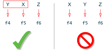
| SUBGRADE f4 f5 f6 | Soil subgrade modulus for mat foundations for use with ALL option in current force/area/length units in Y, X, Z directions respectively. f4, f5 default to f3 if omitted. |
Description
If you want to specify the influence area of a joint yourself and have STAAD simply multiply the area you specified by the sub-grade modulus, use the ELASTIC FOOTING option. Situations where this may be appropriate are such as when a spread footing is located beneath a joint where you want to specify a spring support. A value for f1 (and f2 if its a non-square footing) is required for the FOOTING option.
If you want to have STAAD calculate the influence area for the joint (instead of you specifying an area yourself) and use that area along with the sub-grade modulus to determine the spring stiffness value, use the ELASTIC MAT option. Situations where this may be appropriate are such as when a slab is on soil and carries the weight of the structure above. You may have modeled the entire slab as finite elements and wish to generate spring supports at the nodes of the elements.
The PLATE MAT option is similar to the Elastic Mat except for the method used to compute the influence area for the joints. If your mat consists of plate elements and all of the influence areas are incorporated in the plate areas, then this option is preferable. Enter a list of plates or YRANGE f1 f2 at the beginning of the command, the joint influence areas are then calculated using the same principles as joint forces would be from uniform pressure on these plates. This method overcomes a major limitation of the Delaunay triangle method used in the ELASTIC MAT option, which is that the contour formed by the nodes of the mat must form a convex hull.
The PLATE MAT DIR ALL option is similar to the Plate Mat except that the spring supports are in 3 directions. If the compression only option is also specified, then the compression direction will be assumed to be in the Y direction. If the Y spring at a joint goes slack (lift off), then the X and Z spring stiffnesses for that joint will also be set to zero. Otherwise the X and Z springs act in both directions. The influence area for the X and Z springs is the same as used for the Y spring. Three values of subgrade reaction may be entered, the first is for the Y direction, the second for X and the third for Z.
The keyword DIR is followed by one of the alphabets X, Y or Z (or XONLY, YONLY, or ZONLY) which indicate the direction of resistance of the spring supports. If X or Y or Z is selected then a spring support is generated in that direction plus 3 other directions receive a fixed support, e.g., if Y is selected, then FY is supported by a spring; FX and FZ and MY are fixed supports; and MX and MZ are free. If XONLY, YONLY, or ZONLY are selected then only a spring support in that direction is generated.
The keyword SUBGRADE is followed by the value of the subgrade reaction. The value should be provided in the current unit system signified by the most recent UNIT statement prior to the SUPPORT command.
The PRINT option prints the influence area of each joint.
Use the COMP option generated will be compression only springs
Use the MULTI option to generate multilinear springs. Add the associated multilinear curve input after each MAT command (with the multi option) to describe the displacement-spring constant curve. See TR.27.4 Multilinear Spring Support Specification for additional information on this input format. The actual spring constant used will be the subgrade modulus (f3 entered above) times the influence area (computed by STAAD) times the si values entered in the curve (so the curve stiffness values will likely be between 0.0 and 1.0).
SPRINGS d1 f1 d2 f2 … dn fn
Example
SUPPORTS
1 TO 126 ELASTIC MAT DIREC Y SUBG 200.
1 TO 100 PLATE MAT DIREC Y SUBG 200.
YR -.01 .01 PLA MAT DIR Y SUBG 200 MUL
SPRINGS -100 2.0 -0.51 2.0 -0.50 1.0 0.0 0.0 1000 0.0
The first command above instructs STAAD to internally generate supports for all nodes 1 through 126 with elastic springs. STAAD.Pro first calculates the influence area perpendicular to the global Y axis of each node and then multiplies the corresponding influence area by the soil subgrade modulus of 200.0 to calculate the spring constant to be applied to the node. In the 2nd example, the nodes of plates 1 to 100 are assigned spring supports, generated using a subgrade modulus of 200 units.
Notes
-
A closed surface is generated by the program based on the joint-list that accompanies the ELASTIC MAT command. The area within this closed surface is determined and the share of this area for each node in the list is then calculated.
Hence, while specifying the joint-list, one should make sure that these joints make up a closed surface. Without a proper closed surface, the area calculated for the region may be indeterminate and the spring constant values may be erroneous. Consequently, the list should have at a minimum, 3 nodes.
-
The internal angle formed by 2 adjacent segments connecting 3 consecutive nodes in the list should be less than 180 degrees. In other words, the region should have the shape of a convex polygon. The example below explains the method that may be used to get around a situation where a convex polygon is not available.
-
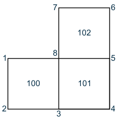
For the model comprised of plate elements 100 to 102 in the figure below, one wishes to generate the spring supports at nodes 1 to 8. However, a single ELASTIC MAT command will not suffice because the internal angle between the edges 1-8 and 8-7 at node 8 is 270 degrees, which violates the requirements of a convex polygon.
So, you should break it up into two commands:
1 2 3 8 ELASTIC MAT DIREC Y SUBG 200.
3 4 5 6 7 8 ELASTIC MAT DIREC Y SUBG 200.
Joints 3 and 8 will hence get the contribution from both of the above commands.
The command works only when the plane of the closed region is parallel to one of the global planes X-Y, Y-Z or X-Z. For regions that are inclined to one of the global planes, the spring constant will have to be evaluated manually and specified using the FIXED BUT type of spring support.