EX. US-12 Moving Load Generation on a Bridge Deck
This example demonstrates generation of load cases for the type of loading known as a moving load. This type of loading occurs classically when the load-causing units move on the structure, as in the case of trucks on a bridge deck. The mobile loads are discretized into several individual immobile load cases at discrete positions. During this process, enormous number of load cases may be created resulting in plenty of output to be sorted. To avoid looking into a lot of output, the maximum force envelope is requested for a few specific members.
This problem is installed with the program by default to C:\Users\Public\Public Documents\STAAD.Pro CONNECT Edition\Samples\Sample Models\US\US-12 Moving Load Generation on a Bridge Deck.STD when you install the program.
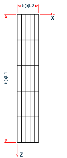
- L1 = 30 ft
- L2 = 5 ft
Actual input is shown in bold lettering followed by explanation.
STAAD FLOOR A SIMPLE BRIDGE DECK
Every input has to start with the term STAAD. The word FLOOR signifies that the structure is a floor structure and the geometry is defined through X and Z axis.
UNITS FEET KIPS
Defines the input units for the data that follows.
    JOINT COORDINATES
    1  0  0  0  6  25  0  0
    R  5  0  0  30
Joint number followed by X, Y, and Z coordinates are provided above. Since this is a floor structure, the Y coordinates are all the same (in this case, zero). The first line generates joints 1 through 6. With the repeat (R) command, the coordinates of the next 30 joints are generated by repeating the pattern of the coordinates of the first 6 joints 5 times with X, Y and Z increments of 0,0, and 9 respectively.
    MEMBER INCIDENCES
    1 1 7 6
    7 1 2 11
    R A 4 11 6
    56 31 32 60
Defines the members by the joints to which they are connected. The fourth number indicates the final member number up to which they will be generated. Repeat all (abbreviated as R A) will create members by repeating the member incidence pattern of the previous 11 members. The number of repetitions to be carried out is provided after the R A command and the member increment and joint increment are defined as 11 and 6 respectively. The fifth line of input defines the member incidences for members 56 to 60.
    MEMBER PROPERTIES AMERICAN
    1 TO 60 TA ST W12X26
Member properties are assigned from the American AISC table for all members. The word ST stands for standard single section.
    SUPPORTS
    1 TO 6 31 TO 36 PINNED
Pinned supports are specified at the above joints. A pinned support is one which can resist only translational forces.
    UNITS INCH
    DEFINE MATERIAL START
    ISOTROPIC STEEL
    E 29000.
    POISSON 0.3
    DENSITY 283e-006
    ALPHA 6e-006
    DAMP 0.03
    TYPE STEEL
    STRENGTH FY 36 FU 58 RY 1.5 RT 1.2
    END DEFINE MATERIAL
    CONSTANT
    MATERIAL STEEL ALL
The input units are changed from FT to INCH. The DEFINE MATERIAL command is used to specify material properties and the CONSTANT is used to assign the material to all members.
    UNIT FEET KIP
    DEFINE MOVING LOAD
    TYPE 1 LOAD  20.  20.  10.  DISTANCE  10.  5.  WIDTH  10.0
The characteristics of the vehicle are defined above in METER and KNS units. The above lines represent the first out of two sets of data required in moving load generation. The type number (1) is a label for identification of the load-causing unit, such as a truck. Three axles (20 20 10) are specified with the LOAD command. The spacing between the axles in the direction of movement (longitudinal direction) is specified after the DISTANCE command. WIDTH is the spacing in the transverse direction, that is, it is the distance between the 2 prongs of an axle of the truck.
LOAD 1
Load case 1 is initiated.
SELF Y -1.0
Selfweight of the structure acting in the negative (due to the factor -1.0) global Y direction is the only component of load case 1.
    LOAD GENERATION  10
    TYPE  1  7.5  0.  0.  ZI  10.
This constitutes the second of the two sets of data required for moving load generation. 10 load cases are generated using the Type 1 vehicle whose characteristics were described earlier. For the first of these load cases, the X, Y and Z location of the reference load (see TR.31.1 Definition of Moving Load System ) have been specified after the command TYPE 1. The Z Increment of 10ft denotes that the vehicle moves along the Z direction and the individual positions which are 10ft apart will be used to generate the remaining 9 load cases.
When defining a moving load in STAAD.Pro, the reference wheel is on the last axle. The first load case which is generated will be the one for which the first axle is just about to enter the bridge. The last load case should be the one for which the last axle is just about to exit the bridge. Thus, the total distance travelled by the reference load will be the length of the vehicle (distance from first axle to last axle) plus the span of the bridge. In this problem, that comes to
(10+5) + 150 = 165 feet.
This example uses 10 ft increments and generates 10 load cases.
However, if you want the vehicle to move forward in 15 feet increments (each 15 foot increment will create a discrete position of the truck on the bridge), it would required (165/15)+1 = 12 cases to be generated.
PERFORM ANALYSIS PRINT LOAD
The above command instructs the program to proceed with the analysis and print the values and positions of all the generated load cases.
PRINT MAXFORCE ENVELOP LIST 3 41 42
A maximum force envelope consisting of the highest forces for each degree of freedom on the listed members will be written into the output file.
FINISH
This command terminates the STAAD run.
Input File
STAAD FLOOR A SIMPLE BRIDGE DECK
UNITS FEET KIPS
JOINT COORDINATES
1 0 0 0 6 25 0 0
R 5 0 0 30
MEMBER INCIDENCES
1 1 7 6
7 1 2 11
R A 4 11 6
56 31 32 60
MEMBER PROPERTIES AMERICAN
1 TO 60 TA ST W12X26
SUPPORTS
1 TO 6 31 TO 36 PINNED
UNITS INCH
DEFINE MATERIAL START
ISOTROPIC STEEL
E 29000
POISSON 0.3
DENSITY 283e-006
ALPHA 6e-006
DAMP 0.03
TYPE STEEL
STRENGTH FY 36 FU 58 RY 1.5 RT 1.2
END DEFINE MATERIAL
CONSTANT
MATERIAL STEEL ALL
UNIT FEET KIP
DEFINE MOVING LOAD
TYPE 1 LOAD 20. 20. 10. DISTANCE 10. 5. WIDTH 10.
LOAD 1
SELF Y -1.0
LOAD GENERATION 10
TYPE 1 7.5 0. 0. ZI 10.
PERFORM ANALYSIS PRINT LOAD
PRINT MAXFORCE ENVELOP LIST 3 41 42
FINISH
STAAD Output File
PAGE NO. 1 **************************************************** * * * STAAD.Pro CONNECT Edition * * Version 22.12.00.*** * * Proprietary Program of * * Bentley Systems, Inc. * * Date= OCT 27, 2022 * * Time= 15: 8:55 * * * * Licensed to: Bentley Systems Inc * **************************************************** 1. STAAD FLOOR A SIMPLE BRIDGE DECK INPUT FILE: US-12 Moving Load Generation on a Bridge Deck.STD 2. UNITS FEET KIPS 3. JOINT COORDINATES 4. 1 0 0 0 6 25 0 0 5. R 5 0 0 30 6. MEMBER INCIDENCES 7. 1 1 7 6 8. 7 1 2 11 9. R A 4 11 6 10. 56 31 32 60 11. MEMBER PROPERTIES AMERICAN 12. 1 TO 60 TA ST W12X26 13. SUPPORTS 14. 1 TO 6 31 TO 36 PINNED 15. UNITS INCH 16. DEFINE MATERIAL START 17. ISOTROPIC STEEL 18. E 29000 19. POISSON 0.3 20. DENSITY 283E-006 21. ALPHA 6E-006 22. DAMP 0.03 23. TYPE STEEL 24. STRENGTH FY 36 FU 58 RY 1.5 RT 1.2 25. END DEFINE MATERIAL 26. CONSTANT 27. MATERIAL STEEL ALL 28. UNIT FEET KIP 29. DEFINE MOVING LOAD 30. TYPE 1 LOAD 20. 20. 10. DISTANCE 10. 5. WIDTH 10. 31. LOAD 1 32. SELF Y -1.0 33. LOAD GENERATION 10 34. TYPE 1 7.5 0. 0. ZI 10. 35. PERFORM ANALYSIS PRINT LOAD A SIMPLE BRIDGE DECK -- PAGE NO. 2 P R O B L E M S T A T I S T I C S ----------------------------------- NUMBER OF JOINTS 36 NUMBER OF MEMBERS 60 NUMBER OF PLATES 0 NUMBER OF SOLIDS 0 NUMBER OF SURFACES 0 NUMBER OF SUPPORTS 12 Using 64-bit analysis engine. SOLVER USED IS THE IN-CORE ADVANCED MATH SOLVER TOTAL PRIMARY LOAD CASES = 11, TOTAL DEGREES OF FREEDOM = 96 TOTAL LOAD COMBINATION CASES = 0 SO FAR. A SIMPLE BRIDGE DECK -- PAGE NO. 3 LOADING 1 ----------- SELFWEIGHT Y -1.000 ACTUAL WEIGHT OF THE STRUCTURE = 27.278 KIP LOADING 2 ----------- MEMBER LOAD - UNIT KIP FEET MEMBER UDL L1 L2 CON L LIN1 LIN2 8 -20.0000 GY 2.50 10 -20.0000 GY 2.50 3 -10.0000 GY 10.00 2 -10.0000 GY 10.00 5 -10.0000 GY 10.00 4 -10.0000 GY 10.00 3 -5.0000 GY 15.00 2 -5.0000 GY 15.00 5 -5.0000 GY 15.00 4 -5.0000 GY 15.00 LOADING 3 ----------- MEMBER LOAD - UNIT KIP FEET MEMBER UDL L1 L2 CON L LIN1 LIN2 3 -10.0000 GY 10.00 2 -10.0000 GY 10.00 5 -10.0000 GY 10.00 4 -10.0000 GY 10.00 3 -10.0000 GY 20.00 2 -10.0000 GY 20.00 5 -10.0000 GY 20.00 4 -10.0000 GY 20.00 3 -5.0000 GY 25.00 2 -5.0000 GY 25.00 5 -5.0000 GY 25.00 4 -5.0000 GY 25.00 LOADING 4 ----------- A SIMPLE BRIDGE DECK -- PAGE NO. 4 MEMBER LOAD - UNIT KIP FEET MEMBER UDL L1 L2 CON L LIN1 LIN2 3 -10.0000 GY 20.00 2 -10.0000 GY 20.00 5 -10.0000 GY 20.00 4 -10.0000 GY 20.00 19 -20.0000 GY 2.50 21 -20.0000 GY 2.50 14 -5.0000 GY 5.00 13 -5.0000 GY 5.00 16 -5.0000 GY 5.00 15 -5.0000 GY 5.00 LOADING 5 ----------- MEMBER LOAD - UNIT KIP FEET MEMBER UDL L1 L2 CON L LIN1 LIN2 19 -20.0000 GY 2.50 21 -20.0000 GY 2.50 14 -10.0000 GY 10.00 13 -10.0000 GY 10.00 16 -10.0000 GY 10.00 15 -10.0000 GY 10.00 14 -5.0000 GY 15.00 13 -5.0000 GY 15.00 16 -5.0000 GY 15.00 15 -5.0000 GY 15.00 LOADING 6 ----------- MEMBER LOAD - UNIT KIP FEET MEMBER UDL L1 L2 CON L LIN1 LIN2 14 -10.0000 GY 10.00 13 -10.0000 GY 10.00 16 -10.0000 GY 10.00 15 -10.0000 GY 10.00 14 -10.0000 GY 20.00 13 -10.0000 GY 20.00 16 -10.0000 GY 20.00 15 -10.0000 GY 20.00 14 -5.0000 GY 25.00 13 -5.0000 GY 25.00 A SIMPLE BRIDGE DECK -- PAGE NO. 5 16 -5.0000 GY 25.00 15 -5.0000 GY 25.00 LOADING 7 ----------- MEMBER LOAD - UNIT KIP FEET MEMBER UDL L1 L2 CON L LIN1 LIN2 14 -10.0000 GY 20.00 13 -10.0000 GY 20.00 16 -10.0000 GY 20.00 15 -10.0000 GY 20.00 30 -20.0000 GY 2.50 32 -20.0000 GY 2.50 25 -5.0000 GY 5.00 24 -5.0000 GY 5.00 27 -5.0000 GY 5.00 26 -5.0000 GY 5.00 LOADING 8 ----------- MEMBER LOAD - UNIT KIP FEET MEMBER UDL L1 L2 CON L LIN1 LIN2 30 -20.0000 GY 2.50 32 -20.0000 GY 2.50 25 -10.0000 GY 10.00 24 -10.0000 GY 10.00 27 -10.0000 GY 10.00 26 -10.0000 GY 10.00 25 -5.0000 GY 15.00 24 -5.0000 GY 15.00 27 -5.0000 GY 15.00 26 -5.0000 GY 15.00 LOADING 9 ----------- MEMBER LOAD - UNIT KIP FEET MEMBER UDL L1 L2 CON L LIN1 LIN2 25 -10.0000 GY 10.00 24 -10.0000 GY 10.00 27 -10.0000 GY 10.00 26 -10.0000 GY 10.00 A SIMPLE BRIDGE DECK -- PAGE NO. 6 25 -10.0000 GY 20.00 24 -10.0000 GY 20.00 27 -10.0000 GY 20.00 26 -10.0000 GY 20.00 25 -5.0000 GY 25.00 24 -5.0000 GY 25.00 27 -5.0000 GY 25.00 26 -5.0000 GY 25.00 LOADING 10 ----------- MEMBER LOAD - UNIT KIP FEET MEMBER UDL L1 L2 CON L LIN1 LIN2 25 -10.0000 GY 20.00 24 -10.0000 GY 20.00 27 -10.0000 GY 20.00 26 -10.0000 GY 20.00 41 -20.0000 GY 2.50 43 -20.0000 GY 2.50 36 -5.0000 GY 5.00 35 -5.0000 GY 5.00 38 -5.0000 GY 5.00 37 -5.0000 GY 5.00 LOADING 11 ----------- MEMBER LOAD - UNIT KIP FEET MEMBER UDL L1 L2 CON L LIN1 LIN2 41 -20.0000 GY 2.50 43 -20.0000 GY 2.50 36 -10.0000 GY 10.00 35 -10.0000 GY 10.00 38 -10.0000 GY 10.00 37 -10.0000 GY 10.00 36 -5.0000 GY 15.00 35 -5.0000 GY 15.00 38 -5.0000 GY 15.00 37 -5.0000 GY 15.00 ************ END OF DATA FROM INTERNAL STORAGE ************ 36. PRINT MAXFORCE ENVELOP LIST 3 41 42 MAXFORCE ENVELOP LIST 3 A SIMPLE BRIDGE DECK -- PAGE NO. 7 MEMBER FORCE ENVELOPE --------------------- ALL UNITS ARE KIP FEET MAX AND MIN FORCE VALUES AMONGST ALL SECTION LOCATIONS MEMB FY/ DIST LD MZ/ DIST LD FZ DIST LD MY DIST LD FX DIST LD 3 MAX 18.03 0.00 3 0.02 0.00 4 0.00 0.00 1 0.00 0.00 1 0.00 0.00 1 MIN -6.97 27.50 3 -373.90 30.00 5 0.00 30.00 11 0.00 30.00 11 0.00 30.00 11 41 MAX 16.33 0.00 10 6.80 5.00 5 0.00 0.00 1 0.00 0.00 1 0.00 0.00 1 MIN -4.08 5.00 11 -109.08 2.50 10 0.00 5.00 11 0.00 5.00 11 0.00 5.00 11 42 MAX 0.06 0.00 1 6.80 0.00 5 0.00 0.00 1 0.00 0.00 1 0.00 0.00 1 MIN -0.06 5.00 1 -99.89 5.00 10 0.00 5.00 11 0.00 5.00 11 0.00 5.00 11 ********** END OF FORCE ENVELOPE FROM INTERNAL STORAGE ********** 37. FINISH *********** END OF THE STAAD.Pro RUN *********** **** DATE= OCT 27,2022 TIME= 15: 8:56 **** A SIMPLE BRIDGE DECK -- PAGE NO. 8 ************************************************************ * For technical assistance on STAAD.Pro, please visit * * http://www.bentley.com/en/support/ * * * * Details about additional assistance from * * Bentley and Partners can be found at program menu * * Help->Technical Support * * * * Copyright (c) Bentley Systems, Inc. * * http://www.bentley.com * ************************************************************