TR.31.1 Definition of Moving Load System
This set of commands may be used to define the moving load system. Enter the DEFINE command only once with up to 100 TYPE commands.
The MOVING LOAD system may be defined in two possible ways: directly within the input file or using an external file.
General Format
DEFINE MOVING LOAD (FILE file-name)
TYPE j { LOAD f1 f2 … fn ( DISTANCE d1 d2 … dn-1 (WIDTH w) ) | load-name (f) }
( DISTANCE d1 d2 … dn-1 (WIDTH w) ) optionally as 2nd set
The FILE option should be used only in the second case when the data is to be read from an external file. The file name should be limited to 24 characters.
Define Moving Load Within the Input File
Use the first TYPE specification. Input Data must be all in one line (as shown above) or two sets of lines. If two sets, then the second set must begin with DIS as shown above. If two sets, then Load and Dist lines may end each line but last of each set with a hyphen (See example).
TYPE j LOAD f1 f2 … fn
DISTANCE d1 d2 … dn-1 (WIDTH w)
Where:
| Parameter | Description |
|---|---|
| TYPE j | moving load system type number (integer limit of 200 types) |
| n | number of loads (eg, axles), 2 to 200. |
| LOAD fi | value of concentrated ith load |
| DISTANCE di | distance between the (i+1)th load and the ith load in the direction of movement |
| WIDTH w | spacing between loads perpendicular to the direction of movement (e.g., the width of vehicle). If left out, one dimensional loading is assumed. This parameter will double the total load since the fi is applied to each wheel. |
Define Moving Load Using an External File
Use the second TYPE specification.
TYPE j load-name (f)
Where:
| Parameter | Description |
|---|---|
| TYPE j | moving load system type no. (integer). |
| load-name | the name of the moving load system (maximum of 24 characters). |
| f | Optional multiplying factor to scale up or down the value of the loads. (default = 1.0) |
Following is a typical file containing the data.
CS200
50. 80. 90. 100.
7. 7. 9.
6.5

Graphical representation of the previous load system
Several load systems may be repeated within the same file.
The STAAD moving load generator assumes:
-
All positive loads are acting in the negative global vertical (Y or Z) direction. The user is advised to set up the structure model accordingly.
-
Resultant direction of movement is determined from the X and Z (or Y if Z is up)increments of movements as provided by the user.
Reference Load
The first specified concentrated load in the moving load system is designated as the reference load. While generating subsequent primary load cases, the initial position of the load system and the direction of movement are defined with respect to the reference load location. Also, when selecting the reference load location with a positive value of Width specified, then the following two views define the reference load location.
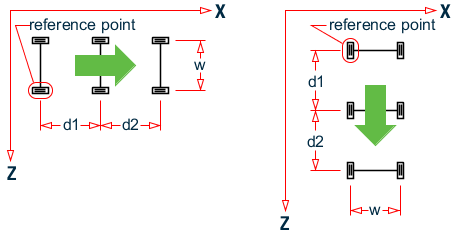
Movement parallel to global X axis; Movement parallel to global Z axis
Notice that in the left view, the reference point is on the positive Z wheel track side; whereas in the right view, the reference point is on the least positive X wheel track side.
Specifying Standard AASHTO Loadings
Truck loads specified in AASHTO specifications are also built in to STAAD.
TYPE j { HS20 | HS15 | H20 | H15 } (f) ( vs )
Where:
| Parameter | Description |
|---|---|
| TYPE j | moving load system type no. (integer). |
| f | Optional multiplying factor to scale up or down the value of the loads. (default = 1.0) |
| vs | variable spacing as defined by AASHTO, for HS series trucks (default = 14 ft.) |