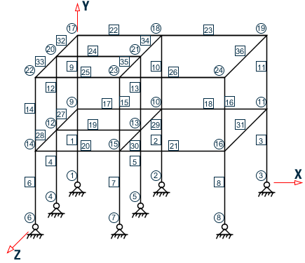
EX. UK-15 Wind and Floor Load Generation on a Space Frame
A space frame is analyzed for loads generated using the built-in wind and floor load generation facilities.
This problem is installed with the program by default to C:\Users\Public\Public Documents\STAAD.Pro CONNECT Edition\Samples\Sample Models\UK\UK-15 Wind and Floor Load Generation on a Space Frame.STD when you install the program.
STAAD SPACE - WIND AND FLOOR LOAD GENERATION
This is a space frame analysis problem. Every STAAD input has to start with the command STAAD. The SPACE specification is used to denote a space (3D) frame.
UNIT METER KNS
The UNIT specification is used to specify the length and/or force units to be used.
    JOINT COORDINATES
    1 0 0 0
    2 4 0 0
    3 9 0 0
    4 0 0 4
    5 4 0 4
    6 0 0 8
    7 4 0 8
    8 9 0 8
    REPEAT ALL 2 0 3.5 0
The JOINT COORDINATE specification is used to specify the X, Y, and Z coordinates of the joints. Note that the REPEAT ALL command has been used to generate joints for the two upper stories each with a Y increment of 3.5 m.
    MEMBER INCIDENCES
    * Columns
    1 1 9 16
    * Beams in the X direction
    17 9 10 18
    19 12 13
    20 14 15 21
    22 17 18 23
    24 20 21
    25 22 23 26
    * Beams in the Z direction
    27 9 12 ; 28 12 14 ; 29 10 13 ; 30 13 15 ; 31 11 16
    32 17 20 ; 33 20 22 ; 34 18 21 ; 35 21 23 ; 36 19 24
The MEMBER INCIDENCE specification is used for specifying member connectivities.
    MEMBER PROPERTIES BRITISH
    1 TO 16 TA ST UB457X191X74
    17 TO 26 TA ST UB457X152X52
    27 TO 36 TA ST UB457X152X52
Properties for all members are specified from the built-in BRITISH steel table. Three different sections have been used.
    UNIT MMS
    DEFINE MATERIAL START
    ISOTROPIC STEEL
    E 210
    POISSON 0.3
    DENSITY 7.6977e-008
    ALPHA 6e-006
    DAMP 0.03
    TYPE STEEL
    STRENGTH FY 0.25 FU 0.4 RY 1.5 RT 1.2
    END DEFINE MATERIAL
    CONSTANTS
    MATERIAL STEEL ALL
    UNIT METER
The DEFINE MATERIAL command is used to specify material properties and the CONSTANT is used to assign the material to all members.
    SUPPORT
    1 TO 8 FIXED BUT MX MZ
The supports of the structure are defined through the SUPPORT specification. Here all the supports are FIXED with releases specified in the MX (rotation about global X-axis) and MZ (rotation about global Z-axis) directions.
    DEFINE WIND LOAD
    TYPE 1
    INTENSITY 1.0 1.5 HEIGHT 3.5 7.0
    EXPOSURE 0.90 YRANGE 6.0 8.0
    EXPOSURE 0.85 JOINT 9 12 14
When a structure has to be analyzed for wind loading, the engineer is confronted with the task of first converting an abstract quantity like wind velocity or wind pressure into concentrated loads at joints, distributed loads on members, or pressure loads on plates. The large number of calculations involved in this conversion can be avoided by making use of STAAD’s wind load generation utility. This utility takes wind pressure at various heights as the input, and converts them to values that can then be used as concentrated forces known as joint loads in specific load cases. The input specification is done in two stages. The first stage is initiated above through the DEFINE WIND LOAD command. The basic parameters of the WIND loading are specified here. All values need to be provided in the current UNIT system. Each wind category is identified with a TYPE number (an identification mark) which is used later to specify load cases.
In this example, two different wind intensities (1.0 KN/sq. m and 1.5 KN/sq. m) are specified for two different height zones (0 to 3.5m and 3.5 to 7.0m). The EXPOSURE specification is used to mitigate or magnify the effect at specific nodes due to special considerations like openings in the structure. In this case, two different exposure factors are specified. The first EXPOSURE specification specifies the exposure factor as 0.9 for all joints within the height range (defined as global Y-range) of 6.0m – 8.0m. The second EXPOSURE specification specifies the exposure factor as 0.85 for joints 9, 12 and 14. In the EXPOSURE factor specification, the joints may be specified directly or through a vertical range specification.
    LOAD 1 WIND LOAD IN X-DIRECTION
    WIND LOAD X 1.2 TYPE 1
This is the second stage of input specification for the wind load generation. The term WIND LOAD and the direction term that follows are used to specify the wind loading in a particular lateral direction. In this case, WIND loading TYPE 1, defined previously, is being applied in the global X-direction with a positive multiplication factor of 1.2 .
    LOAD 2 FLOOR LOAD @ Y = 3.5M AND 7M
    FLOOR LOAD
    YRANGE 3.4 3.6 FLOAD –5.0 XRANGE 0.0 4.0 ZRANGE 0.0 8.0
    YRANGE 3.4 3.6 FLOAD –2.5 XRANGE 4.0 9.0 ZRANGE 0.0 8.0
    YRANGE 6.9 7.1 FLOAD –2.5
In load case 2 in this problem, a floor load generation is performed. In a floor load generation, a pressure load (force per unit area) is converted by the program into specific points forces and distributed forces on the members located in that region. The YRANGE, XRANGE, and ZRANGE specifications are used to define the area of the structure on which the pressure is acting. The FLOAD specification is used to specify the value of that pressure. All values need to be provided in the current UNIT system. For example, in the first line in the above FLOOR LOAD specification, the region is defined as being located within the bounds YRANGE of 3.4 – 3.6 m, XRANGE of 0.0 - 4.0 m and ZRANGE of 0.0 - 8.0 m. The –5.0 signifies that the pressure is 5.0 KN/sq.m. in the negative global Y direction.
The program will identify the members lying within the specified region and derive member loads on these members based on two-way load distribution.
PERFORM ANALYSIS PRINT LOAD DATA
We can view the values and position of the generated loads with the help of the PRINT LOAD DATA command used above along with the PERFORM ANALYSIS command.
    PRINT SUPPORT REACTION
    FINISH
Above commands are self-explanatory.
Input File
STAAD SPACE - WIND AND FLOOR LOAD GENERATION
UNIT METER KNS
JOINT COORDINATES
1 0 0 0
2 4 0 0
3 9 0 0
4 0 0 4
5 4 0 4
6 0 0 8
7 4 0 8
8 9 0 8
REPEAT ALL 2 0 3.5 0
MEMBER INCIDENCES
* Columns
1 1 9 16
* Beams in the X direction
17 9 10 18
19 12 13
20 14 15 21
22 17 18 23
24 20 21
25 22 23 26
* Beams in the Z direction
27 9 12 ; 28 12 14 ; 29 10 13 ; 30 13 15 ; 31 11 16
32 17 20 ; 33 20 22 ; 34 18 21 ; 35 21 23 ; 36 19 24
MEMBER PROPERTIES BRITISH
1 TO 16 TA ST UB457X191X74
17 TO 26 TA ST UB457X152X52
27 TO 36 TA ST UB457X152X52
UNIT MMS
DEFINE MATERIAL START
ISOTROPIC STEEL
E 210
POISSON 0.3
DENSITY 7.6977e-008
ALPHA 6e-006
DAMP 0.03
TYPE STEEL
STRENGTH FY 0.25 FU 0.4 RY 1.5 RT 1.2
END DEFINE MATERIAL
CONSTANTS
MATERIAL STEEL ALL
UNIT METER
SUPPORT
1 TO 8 FIXED BUT MX MZ
DEFINE WIND LOAD
TYPE 1
INTENSITY 1.0 1.5 HEIGHT 3.5 7.0
EXPOSURE 0.90 YRANGE 6.0 8.0
EXPOSURE 0.85 JOINT 9 12 14
LOAD 1 WIND LOAD IN X-DIRECTION
WIND LOAD X 1.2 TYPE 1
LOAD 2 FLOOR LOAD AT Y = 3.5M AND 7M
FLOOR LOAD
YRANGE 3.4 3.6 FLOAD -5.0 XRANGE 0.0 4.0 ZRANGE 0.0 8.0
YRANGE 3.4 3.6 FLOAD -2.5 XRANGE 4.0 9.0 ZRANGE 0.0 8.0
YRANGE 6.9 7.1 FLOAD -2.5
PERFORM ANALYSIS PRINT LOAD DATA
PRINT SUPPORT REACTION
FINISH
STAAD Output File
PAGE NO. 1 **************************************************** * * * STAAD.Pro CONNECT Edition * * Version 22.12.00.*** * * Proprietary Program of * * Bentley Systems, Inc. * * Date= OCT 27, 2022 * * Time= 15: 7:17 * * * * Licensed to: Bentley Systems Inc * **************************************************** 1. STAAD SPACE - WIND AND FLOOR LOAD GENERATION INPUT FILE: UK-15 Wind and Floor Load Generation on a Space Frame.STD 2. UNIT METER KNS 3. JOINT COORDINATES 4. 1 0 0 0 5. 2 4 0 0 6. 3 9 0 0 7. 4 0 0 4 8. 5 4 0 4 9. 6 0 0 8 10. 7 4 0 8 11. 8 9 0 8 12. REPEAT ALL 2 0 3.5 0 13. MEMBER INCIDENCES 14. * COLUMNS 15. 1 1 9 16 16. * BEAMS IN THE X DIRECTION 17. 17 9 10 18 18. 19 12 13 19. 20 14 15 21 20. 22 17 18 23 21. 24 20 21 22. 25 22 23 26 23. * BEAMS IN THE Z DIRECTION 24. 27 9 12 ; 28 12 14 ; 29 10 13 ; 30 13 15 ; 31 11 16 25. 32 17 20 ; 33 20 22 ; 34 18 21 ; 35 21 23 ; 36 19 24 26. MEMBER PROPERTIES BRITISH 27. 1 TO 16 TA ST UB457X191X74 28. 17 TO 26 TA ST UB457X152X52 29. 27 TO 36 TA ST UB457X152X52 30. UNIT MMS 31. DEFINE MATERIAL START 32. ISOTROPIC STEEL 33. E 210 34. POISSON 0.3 35. DENSITY 7.6977E-008 36. ALPHA 6E-006 37. DAMP 0.03 38. TYPE STEEL - WIND AND FLOOR LOAD GENERATION -- PAGE NO. 2 39. STRENGTH FY 0.25 FU 0.4 RY 1.5 RT 1.2 40. END DEFINE MATERIAL 41. CONSTANTS 42. MATERIAL STEEL ALL 43. UNIT METER 44. SUPPORT 45. 1 TO 8 FIXED BUT MX MZ 46. DEFINE WIND LOAD *** NOTE: If any floor diaphragm is present in the model Wind Load definition should be defined after Floor Diaphragm definition. Otherwise wind load generation may be unsuccessful during analysis. 47. TYPE 1 48. INTENSITY 1.0 1.5 HEIGHT 3.5 7.0 49. EXPOSURE 0.90 YRANGE 6.0 8.0 50. EXPOSURE 0.85 JOINT 9 12 14 51. LOAD 1 WIND LOAD IN X-DIRECTION 52. WIND LOAD X 1.2 TYPE 1 53. LOAD 2 FLOOR LOAD AT Y = 3.5M AND 7M 54. FLOOR LOAD 55. YRANGE 3.4 3.6 FLOAD -5.0 XRANGE 0.0 4.0 ZRANGE 0.0 8.0 **NOTE** about Floor/OneWay Loads/Weights. Please note that depending on the shape of the floor you may have to break up the FLOOR/ONEWAY LOAD into multiple commands. For details please refer to Technical Reference Manual Section 5.32.4.2 Note d and/or "5.32.4.3 Note f. 56. YRANGE 3.4 3.6 FLOAD -2.5 XRANGE 4.0 9.0 ZRANGE 0.0 8.0 57. YRANGE 6.9 7.1 FLOAD -2.5 58. PERFORM ANALYSIS PRINT LOAD DATA P R O B L E M S T A T I S T I C S ----------------------------------- NUMBER OF JOINTS 24 NUMBER OF MEMBERS 36 NUMBER OF PLATES 0 NUMBER OF SOLIDS 0 NUMBER OF SURFACES 0 NUMBER OF SUPPORTS 8 Using 64-bit analysis engine. SOLVER USED IS THE IN-CORE ADVANCED MATH SOLVER TOTAL PRIMARY LOAD CASES = 2, TOTAL DEGREES OF FREEDOM = 112 TOTAL LOAD COMBINATION CASES = 0 SO FAR. - WIND AND FLOOR LOAD GENERATION -- PAGE NO. 3 - WIND AND FLOOR LOAD GENERATION -- PAGE NO. 4 LOADING 1 WIND LOAD IN X-DIRECTION ----------- JOINT LOAD - UNIT KNS METE JOINT FORCE-X FORCE-Y FORCE-Z MOM-X MOM-Y MOM-Z 1 4.20 0.00 0.00 0.00 0.00 0.00 4 8.40 0.00 0.00 0.00 0.00 0.00 6 4.20 0.00 0.00 0.00 0.00 0.00 9 8.93 0.00 0.00 0.00 0.00 0.00 12 17.85 0.00 0.00 0.00 0.00 0.00 14 8.93 0.00 0.00 0.00 0.00 0.00 17 5.67 0.00 0.00 0.00 0.00 0.00 20 11.34 0.00 0.00 0.00 0.00 0.00 22 5.67 0.00 0.00 0.00 0.00 0.00 LOADING 2 FLOOR LOAD AT Y = 3.5M AND 7M ----------- MEMBER LOAD - UNIT KNS METE MEMBER UDL L1 L2 CON L LIN1 LIN2 17 -0.1563 GY 0.17 17 -0.4688 GY 0.39 17 -0.7812 GY 0.63 17 -1.0938 GY 0.88 17 -1.4062 GY 1.13 17 -1.7188 GY 1.38 17 -2.0312 GY 1.63 17 -2.3438 GY 1.88 17 -2.3438 GY 2.12 17 -2.0312 GY 2.37 17 -1.7188 GY 2.62 17 -1.4062 GY 2.87 17 -1.0938 GY 3.12 17 -0.7812 GY 3.37 17 -0.4688 GY 3.61 17 -0.1563 GY 3.83 29 -0.1563 GY 0.17 29 -0.4688 GY 0.39 29 -0.7812 GY 0.63 29 -1.0938 GY 0.88 29 -1.4062 GY 1.13 29 -1.7188 GY 1.38 29 -2.0312 GY 1.63 29 -2.3438 GY 1.88 29 -2.3438 GY 2.12 29 -2.0312 GY 2.37 29 -1.7188 GY 2.62 - WIND AND FLOOR LOAD GENERATION -- PAGE NO. 5 29 -1.4062 GY 2.87 29 -1.0938 GY 3.12 29 -0.7812 GY 3.37 29 -0.4688 GY 3.61 29 -0.1563 GY 3.83 19 -0.1563 GY 0.17 19 -0.4688 GY 0.39 19 -0.7812 GY 0.63 19 -1.0938 GY 0.88 19 -1.4062 GY 1.13 19 -1.7188 GY 1.38 19 -2.0312 GY 1.63 19 -2.3438 GY 1.88 19 -2.3438 GY 2.12 19 -2.0312 GY 2.37 19 -1.7188 GY 2.62 19 -1.4062 GY 2.87 19 -1.0938 GY 3.12 19 -0.7812 GY 3.37 19 -0.4688 GY 3.61 19 -0.1563 GY 3.83 27 -0.1563 GY 0.17 27 -0.4688 GY 0.39 27 -0.7812 GY 0.63 27 -1.0938 GY 0.88 27 -1.4062 GY 1.13 27 -1.7188 GY 1.38 27 -2.0312 GY 1.63 27 -2.3438 GY 1.88 27 -2.3438 GY 2.12 27 -2.0312 GY 2.37 27 -1.7188 GY 2.62 27 -1.4062 GY 2.87 27 -1.0938 GY 3.12 27 -0.7812 GY 3.37 27 -0.4688 GY 3.61 27 -0.1563 GY 3.83 19 -0.1563 GY 0.17 19 -0.4688 GY 0.39 19 -0.7812 GY 0.63 19 -1.0938 GY 0.88 19 -1.4062 GY 1.13 19 -1.7188 GY 1.38 19 -2.0312 GY 1.63 19 -2.3438 GY 1.88 19 -2.3438 GY 2.12 19 -2.0312 GY 2.37 19 -1.7188 GY 2.62 19 -1.4062 GY 2.87 19 -1.0938 GY 3.12 19 -0.7812 GY 3.37 19 -0.4688 GY 3.61 19 -0.1563 GY 3.83 30 -0.1563 GY 0.17 30 -0.4688 GY 0.39 30 -0.7812 GY 0.63 - WIND AND FLOOR LOAD GENERATION -- PAGE NO. 6 30 -1.0938 GY 0.88 30 -1.4062 GY 1.13 30 -1.7188 GY 1.38 30 -2.0312 GY 1.63 30 -2.3438 GY 1.88 30 -2.3438 GY 2.12 30 -2.0312 GY 2.37 30 -1.7188 GY 2.62 30 -1.4062 GY 2.87 30 -1.0938 GY 3.12 30 -0.7812 GY 3.37 30 -0.4688 GY 3.61 30 -0.1563 GY 3.83 20 -0.1563 GY 0.17 20 -0.4688 GY 0.39 20 -0.7812 GY 0.63 20 -1.0938 GY 0.88 20 -1.4062 GY 1.13 20 -1.7188 GY 1.38 20 -2.0312 GY 1.63 20 -2.3438 GY 1.88 20 -2.3438 GY 2.12 20 -2.0312 GY 2.37 20 -1.7188 GY 2.62 20 -1.4062 GY 2.87 20 -1.0938 GY 3.12 20 -0.7812 GY 3.37 20 -0.4688 GY 3.61 20 -0.1563 GY 3.83 28 -0.1563 GY 0.17 28 -0.4688 GY 0.39 28 -0.7812 GY 0.63 28 -1.0938 GY 0.88 28 -1.4062 GY 1.13 28 -1.7188 GY 1.38 28 -2.0312 GY 1.63 28 -2.3438 GY 1.88 28 -2.3438 GY 2.12 28 -2.0312 GY 2.37 28 -1.7188 GY 2.62 28 -1.4062 GY 2.87 28 -1.0938 GY 3.12 28 -0.7812 GY 3.37 28 -0.4688 GY 3.61 28 -0.1563 GY 3.83 MEMBER LOAD - UNIT KNS METE MEMBER UDL L1 L2 CON L LIN1 LIN2 18 -0.1221 GY 0.21 18 -0.3662 GY 0.49 18 -0.6104 GY 0.79 18 -0.8545 GY 1.10 18 -1.0986 GY 1.41 - WIND AND FLOOR LOAD GENERATION -- PAGE NO. 7 18 -1.3428 GY 1.72 18 -1.5869 GY 2.04 18 -1.8311 GY 2.35 18 -1.8311 GY 2.65 18 -1.5869 GY 2.96 18 -1.3428 GY 3.28 18 -1.0986 GY 3.59 18 -0.8545 GY 3.90 18 -0.6104 GY 4.21 18 -0.3662 GY 4.51 18 -0.1221 GY 4.79 31 -0.1221 GY 0.21 31 -0.3662 GY 0.49 31 -0.6104 GY 0.79 31 -0.8545 GY 1.10 31 -1.0986 GY 1.41 31 -1.3428 GY 1.72 31 -1.5869 GY 2.04 31 -1.8311 GY 2.35 31 -6.2500 GY 2.50 5.50 31 -1.8311 GY 5.65 31 -1.5869 GY 5.96 31 -1.3428 GY 6.28 31 -1.0986 GY 6.59 31 -0.8545 GY 6.90 31 -0.6104 GY 7.21 31 -0.3662 GY 7.51 31 -0.1221 GY 7.79 21 -0.1221 GY 0.21 21 -0.3662 GY 0.49 21 -0.6104 GY 0.79 21 -0.8545 GY 1.10 21 -1.0986 GY 1.41 21 -1.3428 GY 1.72 21 -1.5869 GY 2.04 21 -1.8311 GY 2.35 21 -1.8311 GY 2.65 21 -1.5869 GY 2.96 21 -1.3428 GY 3.28 21 -1.0986 GY 3.59 21 -0.8545 GY 3.90 21 -0.6104 GY 4.21 21 -0.3662 GY 4.51 21 -0.1221 GY 4.79 30 -1.8311 GY 1.65 30 -1.5869 GY 1.96 30 -1.3428 GY 2.28 30 -1.0986 GY 2.59 30 -0.8545 GY 2.90 30 -0.6104 GY 3.21 30 -0.3662 GY 3.51 30 -0.1221 GY 3.79 30 -6.2500 GY 0.00 1.50 29 -0.1221 GY 0.21 29 -0.3662 GY 0.49 29 -0.6104 GY 0.79 - WIND AND FLOOR LOAD GENERATION -- PAGE NO. 8 29 -0.8545 GY 1.10 29 -1.0986 GY 1.41 29 -1.3428 GY 1.72 29 -1.5869 GY 2.04 29 -1.8311 GY 2.35 29 -6.2500 GY 2.50 4.00 MEMBER LOAD - UNIT KNS METE MEMBER UDL L1 L2 CON L LIN1 LIN2 22 -0.0781 GY 0.17 22 -0.2344 GY 0.39 22 -0.3906 GY 0.63 22 -0.5469 GY 0.88 22 -0.7031 GY 1.13 22 -0.8594 GY 1.38 22 -1.0156 GY 1.63 22 -1.1719 GY 1.88 22 -1.1719 GY 2.12 22 -1.0156 GY 2.37 22 -0.8594 GY 2.62 22 -0.7031 GY 2.87 22 -0.5469 GY 3.12 22 -0.3906 GY 3.37 22 -0.2344 GY 3.61 22 -0.0781 GY 3.83 34 -0.0781 GY 0.17 34 -0.2344 GY 0.39 34 -0.3906 GY 0.63 34 -0.5469 GY 0.88 34 -0.7031 GY 1.13 34 -0.8594 GY 1.38 34 -1.0156 GY 1.63 34 -1.1719 GY 1.88 34 -1.1719 GY 2.12 34 -1.0156 GY 2.37 34 -0.8594 GY 2.62 34 -0.7031 GY 2.87 34 -0.5469 GY 3.12 34 -0.3906 GY 3.37 34 -0.2344 GY 3.61 34 -0.0781 GY 3.83 24 -0.0781 GY 0.17 24 -0.2344 GY 0.39 24 -0.3906 GY 0.63 24 -0.5469 GY 0.88 24 -0.7031 GY 1.13 24 -0.8594 GY 1.38 24 -1.0156 GY 1.63 24 -1.1719 GY 1.88 24 -1.1719 GY 2.12 24 -1.0156 GY 2.37 24 -0.8594 GY 2.62 24 -0.7031 GY 2.87 - WIND AND FLOOR LOAD GENERATION -- PAGE NO. 9 24 -0.5469 GY 3.12 24 -0.3906 GY 3.37 24 -0.2344 GY 3.61 24 -0.0781 GY 3.83 32 -0.0781 GY 0.17 32 -0.2344 GY 0.39 32 -0.3906 GY 0.63 32 -0.5469 GY 0.88 32 -0.7031 GY 1.13 32 -0.8594 GY 1.38 32 -1.0156 GY 1.63 32 -1.1719 GY 1.88 32 -1.1719 GY 2.12 32 -1.0156 GY 2.37 32 -0.8594 GY 2.62 32 -0.7031 GY 2.87 32 -0.5469 GY 3.12 32 -0.3906 GY 3.37 32 -0.2344 GY 3.61 32 -0.0781 GY 3.83 23 -0.1221 GY 0.21 23 -0.3662 GY 0.49 23 -0.6104 GY 0.79 23 -0.8545 GY 1.10 23 -1.0986 GY 1.41 23 -1.3428 GY 1.72 23 -1.5869 GY 2.04 23 -1.8311 GY 2.35 23 -1.8311 GY 2.65 23 -1.5869 GY 2.96 23 -1.3428 GY 3.28 23 -1.0986 GY 3.59 23 -0.8545 GY 3.90 23 -0.6104 GY 4.21 23 -0.3662 GY 4.51 23 -0.1221 GY 4.79 36 -0.1221 GY 0.21 36 -0.3662 GY 0.49 36 -0.6104 GY 0.79 36 -0.8545 GY 1.10 36 -1.0986 GY 1.41 36 -1.3428 GY 1.72 36 -1.5869 GY 2.04 36 -1.8311 GY 2.35 36 -6.2500 GY 2.50 5.50 36 -1.8311 GY 5.65 36 -1.5869 GY 5.96 36 -1.3428 GY 6.28 36 -1.0986 GY 6.59 36 -0.8545 GY 6.90 36 -0.6104 GY 7.21 36 -0.3662 GY 7.51 36 -0.1221 GY 7.79 26 -0.1221 GY 0.21 26 -0.3662 GY 0.49 26 -0.6104 GY 0.79 - WIND AND FLOOR LOAD GENERATION -- PAGE NO. 10 26 -0.8545 GY 1.10 26 -1.0986 GY 1.41 26 -1.3428 GY 1.72 26 -1.5869 GY 2.04 26 -1.8311 GY 2.35 26 -1.8311 GY 2.65 26 -1.5869 GY 2.96 26 -1.3428 GY 3.28 26 -1.0986 GY 3.59 26 -0.8545 GY 3.90 26 -0.6104 GY 4.21 26 -0.3662 GY 4.51 26 -0.1221 GY 4.79 35 -1.8311 GY 1.65 35 -1.5869 GY 1.96 35 -1.3428 GY 2.28 35 -1.0986 GY 2.59 35 -0.8545 GY 2.90 35 -0.6104 GY 3.21 35 -0.3662 GY 3.51 35 -0.1221 GY 3.79 35 -6.2500 GY 0.00 1.50 34 -0.1221 GY 0.21 34 -0.3662 GY 0.49 34 -0.6104 GY 0.79 34 -0.8545 GY 1.10 34 -1.0986 GY 1.41 34 -1.3428 GY 1.72 34 -1.5869 GY 2.04 34 -1.8311 GY 2.35 34 -6.2500 GY 2.50 4.00 24 -0.0781 GY 0.17 24 -0.2344 GY 0.39 24 -0.3906 GY 0.63 24 -0.5469 GY 0.88 24 -0.7031 GY 1.13 24 -0.8594 GY 1.38 24 -1.0156 GY 1.63 24 -1.1719 GY 1.88 24 -1.1719 GY 2.12 24 -1.0156 GY 2.37 24 -0.8594 GY 2.62 24 -0.7031 GY 2.87 24 -0.5469 GY 3.12 24 -0.3906 GY 3.37 24 -0.2344 GY 3.61 24 -0.0781 GY 3.83 35 -0.0781 GY 0.17 35 -0.2344 GY 0.39 35 -0.3906 GY 0.63 35 -0.5469 GY 0.88 35 -0.7031 GY 1.13 35 -0.8594 GY 1.38 35 -1.0156 GY 1.63 35 -1.1719 GY 1.88 35 -1.1719 GY 2.12 - WIND AND FLOOR LOAD GENERATION -- PAGE NO. 11 35 -1.0156 GY 2.37 35 -0.8594 GY 2.62 35 -0.7031 GY 2.87 35 -0.5469 GY 3.12 35 -0.3906 GY 3.37 35 -0.2344 GY 3.61 35 -0.0781 GY 3.83 25 -0.0781 GY 0.17 25 -0.2344 GY 0.39 25 -0.3906 GY 0.63 25 -0.5469 GY 0.88 25 -0.7031 GY 1.13 25 -0.8594 GY 1.38 25 -1.0156 GY 1.63 25 -1.1719 GY 1.88 25 -1.1719 GY 2.12 25 -1.0156 GY 2.37 25 -0.8594 GY 2.62 25 -0.7031 GY 2.87 25 -0.5469 GY 3.12 25 -0.3906 GY 3.37 25 -0.2344 GY 3.61 25 -0.0781 GY 3.83 33 -0.0781 GY 0.17 33 -0.2344 GY 0.39 33 -0.3906 GY 0.63 33 -0.5469 GY 0.88 33 -0.7031 GY 1.13 33 -0.8594 GY 1.38 33 -1.0156 GY 1.63 33 -1.1719 GY 1.88 33 -1.1719 GY 2.12 33 -1.0156 GY 2.37 33 -0.8594 GY 2.62 33 -0.7031 GY 2.87 33 -0.5469 GY 3.12 33 -0.3906 GY 3.37 33 -0.2344 GY 3.61 33 -0.0781 GY 3.83 ************ END OF DATA FROM INTERNAL STORAGE ************ 59. PRINT SUPPORT REACTION SUPPORT REACTION - WIND AND FLOOR LOAD GENERATION -- PAGE NO. 12 SUPPORT REACTIONS -UNIT KNS METE STRUCTURE TYPE = SPACE ----------------- JOINT LOAD FORCE-X FORCE-Y FORCE-Z MOM-X MOM-Y MOM Z 1 1 -9.58 -11.46 -0.01 0.00 -0.01 0.00 2 0.80 25.69 0.16 0.00 -0.00 0.00 2 1 -6.70 3.60 0.01 0.00 -0.00 0.00 2 -0.15 52.75 0.26 0.00 -0.00 0.00 3 1 -5.01 7.95 0.00 0.00 0.00 0.00 2 -0.71 49.30 1.16 0.00 0.00 0.00 4 1 -20.54 -28.15 0.00 0.00 0.00 0.00 2 1.72 66.85 -0.00 0.00 0.00 0.00 5 1 -12.05 27.97 0.00 0.00 0.00 0.00 2 -1.61 117.68 -0.00 0.00 0.00 0.00 6 1 -9.58 -11.46 0.01 0.00 0.01 0.00 2 0.80 25.69 -0.16 0.00 0.00 0.00 7 1 -6.70 3.60 -0.01 0.00 0.00 0.00 2 -0.15 52.75 -0.26 0.00 0.00 0.00 8 1 -5.01 7.95 -0.00 0.00 -0.00 0.00 2 -0.71 49.30 -1.16 0.00 -0.00 0.00 ************** END OF LATEST ANALYSIS RESULT ************** 60. FINISH *********** END OF THE STAAD.Pro RUN *********** **** DATE= OCT 27,2022 TIME= 15: 7:18 **** - WIND AND FLOOR LOAD GENERATION -- PAGE NO. 13 ************************************************************ * For technical assistance on STAAD.Pro, please visit * * http://www.bentley.com/en/support/ * * * * Details about additional assistance from * * Bentley and Partners can be found at program menu * * Help->Technical Support * * * * Copyright (c) Bentley Systems, Inc. * * http://www.bentley.com * ************************************************************